Connect GND to anywhere big metal on the camera.
Then use the RX pin and connect it to each pin on the 4 pin header (one by one), power up the camera and see if you are getting annything.
Don't connect anything else.
If you see gibberish, try the other pins still.
If there is only one pin that gives you gibberish than your settings must be wrong.
If you don't get anything at all try again with the TX pin instead, as sometimes they swap them.
You already covered this but just a reminder to @KCulver you need to connect the tx pin on the adapter to the rx pin on the camera and the rx pin on the adapter to the tx pin on the camera.
You can also try connecting a wire between tx and rx on your adapter and opening the connection. this will echo anything you type back to you it's a simple way to test that your adapter and software are working correctly.
@KCulver it WILL NOT function without ground connected
Hi cor35vet, I finally got a chance to get a USB-to-RS232 adapter and make the connection. However, with the camera powered on, I can never get any response from the Putty terminal screen. Here is my connection setup. Please advise. Thanks a lot.
Yikes! You're lucky you didn't connect ground when you did that or you could have fried the whole the camera (ground is required for the connection to actually function).
I originally connected the USB dongle using an USB extension cord. I kept getting gibberish on the screen. Try to connect the USB dongle directly to the USB port of your PC.
Also, if you're using Windows, make sure that the connection settings in device manager match the ones in Putty.
Using a usb extension cable really shouldn't matter as long it's decent quality, in fact it's normal operating procedure for one of these low voltage serial adapters.
I did try a direct connection to my laptop and keep getting the same scrolling gibberish. I just don't know enough as to what to expect in order to rule out anything. I did test the dongle by shorting the rx/tx pins and was able to type directly in the console. I just wish there was a way that I could know the UART pinouts from the pcb board. Also let me ask this. What is the best way to connect ground? From the ground pin on the dongle to camera ground plane? That is what I have been doing. Anyway I keep trying - really need to have this skill since i am dealing with this Chinese hardware.
I broke my camera by accident while messing with the firmware and had to recover it.
Since I am not the only one that this has happened to and will probably not stay the last one: Here is a simple tutorial on how to unbrick your Dahua IP camera.
Warning: The cameras serial port is 3.3 Volts, do not try to use RS232 which is 12 Volts!!
For this you need:
A broken camera with the bootloader still working - assume it is working if you don't know.
If you know it is not working, look *here* and don't be afraid to ask
A serial UART device, such as:
Raspberry Pi or any other microcontroller/devboard with UART
USB to serial converter: These can be bought for *very* cheap from china:
For example the CP2102 USB to UART bridge worked very well for me
You should be able to figure this out by using Google.
First of all you have to locate the RX (receive) and TX (transmit) pins on your camera:
On my IPC-HFW4431M camera (and probably all other generation 3/Eos cameras) they can be found very easily:
For other cameras this page on the Dahua wiki should prove useful: ResetIPCamera - Dahua Wiki
On most devices the serial port consists of 4 pins/pinheads which are made up of VCC,GND,RX,TX.
You can connect the GND (Ground, -) of your dongle to the metal casing of your camera.
VCC (+) should not be connected.
You can identify the TX (transmit) pin of your camera by connecting it (press wire against pin) with the RX pin of your serial device.
Though be aware that some dongles swap the labels like so:
Dongle says RX, but it is actually TX of the dongle and wants to be connected with RX of the other device.
If you power up your camera and see text scrolling down your terminal you have found the right pin, keep trying if you don't ^^
Now put a brick on your * key with your terminal window in focus.
Try to find the RX (receive) pin of the camera and connect it with the TX pin of your dongle.
Power up the camera, wait a second, if you see the following message you have succeeded:
Code:
U-Boot 2010.06-svn3089 (Jul 22 2016 - 19:15:59)
DRAM:  1 GiB
gBootLogPtr:80b80008.
Check spi flash controller v350... Found
Spi(cs1) ID: 0xC8 0x40 0x18 0xC8 0x40 0x18
Spi(cs1): Block:64KB Chip:16MB Name:"GD25Q128"
partition file version 2
rootfstype squashfs root /dev/mtdblock7
In:    serial
Out:   serial
Err:   serial
TEXT_BASE:81000000
Net:   PHY found at 3

Hit any key to stop autoboot:  0
> **********************
Type help to see all available commands:
Code:
> help
?       - alias for 'help'
base    - print or set address offset
boot    - boot default, i.e., run 'bootcmd'
bootd   - boot default, i.e., run 'bootcmd'
bootf   - boot from flash
bootm   - boot application image from memory
bootp   - boot image via network using BOOTP/TFTP protocol
cfgRestore- erase  config and backup partition.

cmp     - memory compare
cp      - memory copy
crc32   - checksum calculation
crypt   - crypt
erasepart- erasepart

exit    - exit script
false   - do nothing, unsuccessfully
fatinfo - print information about filesystem
fatload - load binary file from a dos filesystem
fatls   - list files in a directory (default /)
flwrite - flwrite - write data into FLASH memory

fsinfo  - print information about filesystems
fsload  - load binary file from a filesystem image
go      - start application at address 'addr'
help    - print command description/usage
hwid    - hwid      - set hardware id and save to flash

kload   - kload  - load uImage file from parttion

lip     - lip      - set local ip address but not save to flash

loadb   - load binary file over serial line (kermit mode)
loady   - load binary file over serial line (ymodem mode)
logsend - get log buf
loop    - infinite loop on address range
ls      - list files in a directory (default /)
mac     - mac      - set mac address and save to flash

md      - memory display
memsize - memsize        - set mem size

mii     - MII utility commands
mm      - memory modify (auto-incrementing address)
mtest   - simple RAM read/write test
mw      - memory write (fill)
nm      - memory modify (constant address)
partition- print partition information
ping    - send ICMP ECHO_REQUEST to network host
printenv- print environment variables
rarpboot- boot image via network using RARP/TFTP protocol
rdefault- rdefault    -recover default env

reset   - Perform RESET of the CPU
run     - run commands in an environment variable
saveenv - save environment variables to persistent storage
setenv  - set environment variables
sf      - SPI flash sub-system
showvar - print local hushshell variables
sip     - sip      - set server ip address but not save to flash

sleep   - delay execution for some time
smi     - MII utility commands
sync_uboot- sync_uboot - sync uboot to uboot-bak

test    - minimal test like /bin/sh
tftpboot- tftpboot- boot image via network using TFTP protocol
true    - do nothing, successfully
uartUp  - uartUp- update image via uart using uart4

usleep  - delay execution for some time
version - print monitor version
>
The guys from Dahua have done something right for once and added some helpful commands for us, type printenv to print the U-Boot Environment, you should be able to find these lines among other stuff:
gatewayip -> The IP address of your networks gateway (router)
setenv gatewayip 192.168.1.1
netmask -> The netmask/subnet of your network
setenv netmask 255.255.255.0
servip -> The IP address of your computer (that runs the TFTP server)
setenv serverip 192.168.1.4
You can test the connection to your PC by runing ping $serverip
Code:
> ping $serverip
ETH0: PHY(phyaddr=-1, rmii) link UP: DUPLEX=FULL : SPEED=100M
MAC:   00-12-34-56-78-91
Using gmac device
host 192.168.1.4 is alive
(Okay actually I don't even know if Windows will reply to pings by default - so I guess you can ignore this for now)
Extract the firmware image for your camera somewhere, use some ZIP program like 7zip. It might complain about invalid ZIP file (since Dahua changes the ZIP header from PK to DH) you can either fix the ZIP with a HEX editor or use another program to unzip it.
Start the TFTP server and point it to the files you have extracted from the firmware image.
And now for the final part: Flashing the firmware!
I'll flash following partitions in order:
romfs (root linux filesystem with busybox)
kernel (The holy Linux Kernel)
user (Dahuas programs and kernel modules)
web (Webinterface)
partition ("Partition table" - text files which describe the layout on the flash chip)
custom (Language files)
Do not flash the bootloader! There is no need to and when you fuck that up recovering is a lot harder.
Run following commands one after eachother:
Code:
run dr
run dk
run du
run dw
run dp
run dc
Example output:
Code:
> run dr
ETH0: PHY(phyaddr=-1, rmii) link UP: DUPLEX=FULL : SPEED=100M
MAC:   3C-EF-8C-FA-E7-88
Using gmac device
TFTP from server 192.168.1.4; our IP address is 192.168.1.108
Download Filename 'romfs-x.squashfs.img'.
Download to address: 0x82000000
Downloading: #################################################
done
Bytes transferred = 909376 (de040 hex)

## Checking Image at 82000000 ...
   Legacy image found
   Image Name:   romfs
   Image Type:   ARM Linux Standalone Program (gzip compressed)
   Data Size:    909312 Bytes = 888 KiB
   Load Address: 002f0000
   Entry Point:  003d0000
   Verifying Checksum ... OK
Programing start at: 0x002f0000
SPI probe: 16384 KiB hi_sfc at 0:0 is now current device

write : 0%
write : 0%
write : 7%
write : 14%
write : 21%
write : 28%
write : 35%
write : 42%
write : 50%
write : 57%
write : 64%
write : 71%
write : 78%
write : 85%
write : 92%
write : 100%
done
You can run save if you want to save the environment variables you have set (ipaddr, servip, ..).
I also recommend doing setenv dh_keyboard 0 and saving with save.
Run boot to boot the camera
Congratulations!
(If you just read this for fun and do not have a bricked camera I still suggest you to buy a serial UART dongle, they're cheaper than most snacks and you can save lots of devices with it!)
That's a great post, well done and thanks for sharing!
If / when I get a Dahua camera (not convinced I'll get good functionality with Hikvision NVRs) I suspect it will come in very useful.
Dahua have included / retained a lot of useful functionality in their U-boot, unlike Hikvision who strip it to an almost useless state in pursuit of their 'let's make using our products difficult for our knowledgeable customers' stupid strategy.
Question, regarding the "*" key in the terminal window, is this key applicable for all terminal software like putty. If not, what should I look for in the software documentation to find this key. What is this keystroke for? Thanks.
As an eBay Associate IPCamTalk earns from qualifying purchases.
Question, regarding the "*" key in the terminal window, is this key applicable for all terminal software like putty. If not, what should I look for in the software documentation to find this key. What is this keystroke for? Thanks.
The boot loader has an automatic baud rate detection function. Holding down the * key on the keyboard after you've opened the serial connection allows the camera to match the computer's baud rate easily.
I'm glad I found this Thread because I have an big problem with my VTO2000A. After I've flashed an modified Firmware I can't get any connection to it. When I sniff ports I will see nothing. It seems to be that there is no open port. Because of this the only way to rescue my doorbell is to unbrick it with and USB-TTL.
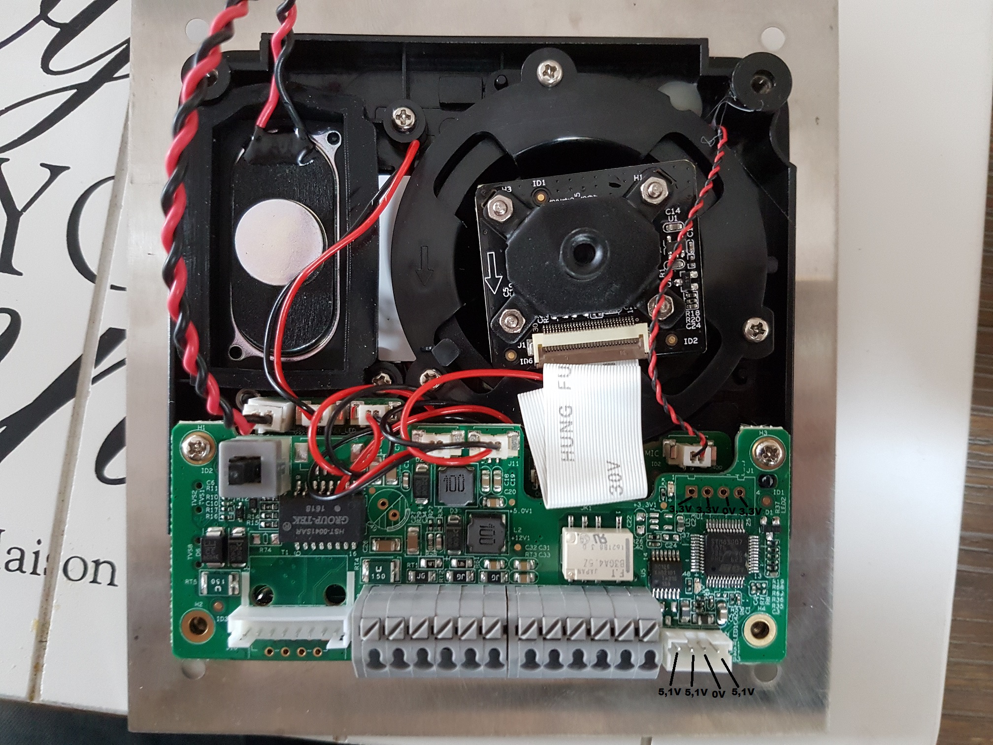
But I couldn't find the serial port. On backside there is an port which Dahua calls "Project Port" or "Cascading Port".
I measured the voltage on the pins and 3 of 4 have 5V. Could this be the serial Port?
I've made picture of the port where I think one of them could be the serial port.
Could one of them be the serial port which I need or how can I detect it?
the one with 3.3V is likely serial, two ports on the left should be rx and tx, try touching them with the receive pin of your usb ttl dongle and power up the device.
Though if you somehow killed the bootloader that won't work but lets assume that is still intact.
Thx
My USB-TTL-Dongle is still in Shipping progress
You mean that the first on the left (square one) should be TX or RX?
When I use my Multimeter an hold it on that measure Point on Boot Process the Voltage must be varying the Voltage because data will be transfered? Is this right to proof if it is really TX or RX with Multimeter?
Then I can manage everything till my Dongle is here.
An oscilloscope: yes.
Actually had to decode a message at school on an oscilloscope which the prof. sent over serial in the lab.
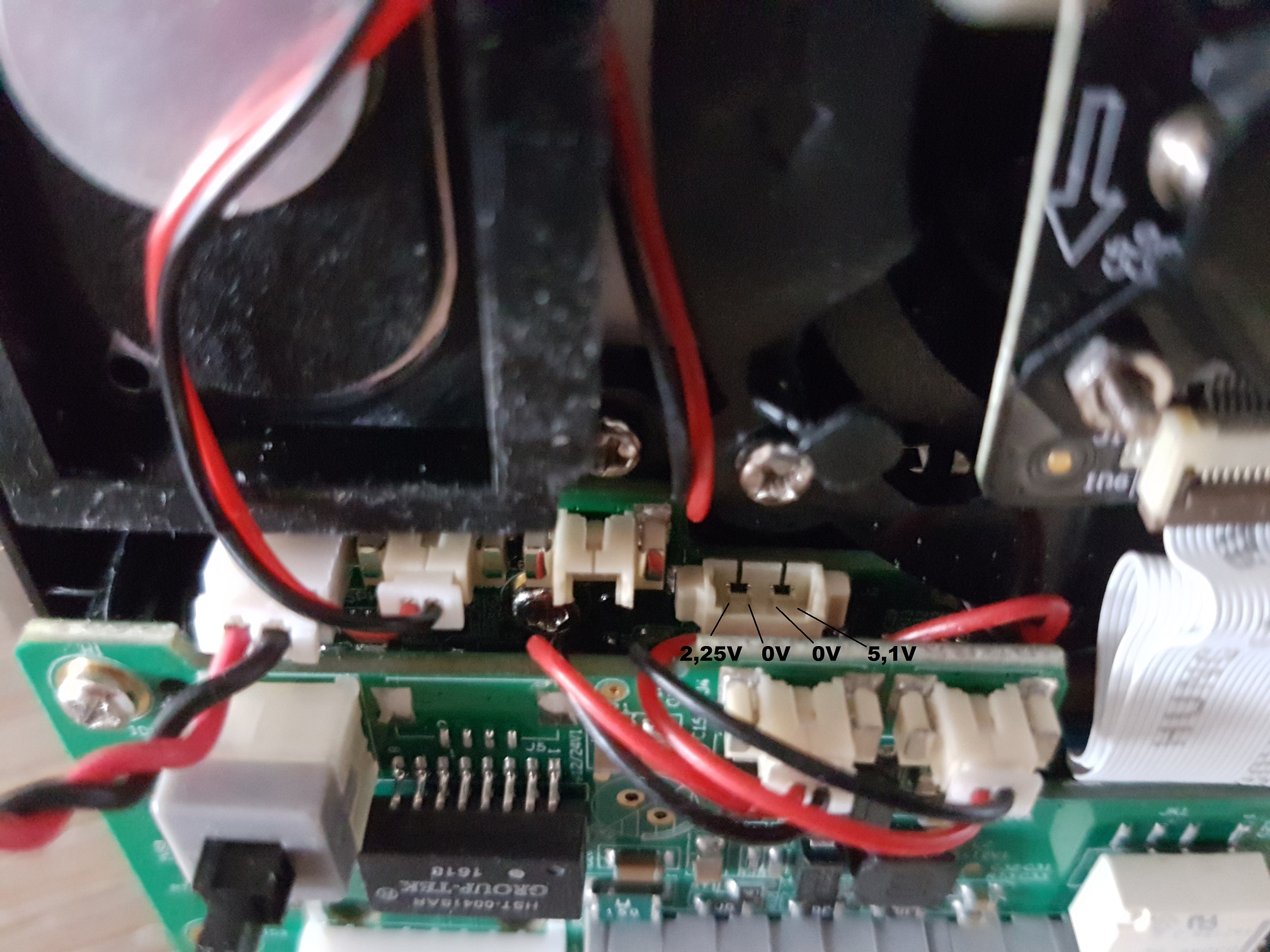
Edit: Yeah, I think the two left ones should be what you want. RX / TX
Easiest is to just try to find TX (the transmitting one with the receiving RX of your dongle) and then connect the TX of your dongle to other one.
Make sure to try all different combinations as sometimes the labels are swapped.
I can confirm that the little connector on the bottom board is the serial port. The one second from the left is TX. I've not yet had a chance to figure out the RX as the connector is so tiny I can only plug into one pin at a time
Did you manage to unbrick your doorbell as I have also just bricked mine trying to upload a modified firmware.
Sorry for the late reply but I couldn't log in. Don't know why. Everytime I get an Error Message when I push the Login-Button.
I have send my bricked VTO to an member of an other forum, because he want to try to unbick it. But then he has no time an didn't send it back.
The pictures I've made where done with my new one and I don't wanna make experiments with it.


")

 but lets assume that is still intact.