Anyone here an electrical engineer?

wantafastz28

Getting comfortable
Joined
Nov 18, 2016
Messages
550
Reaction score
253
Location
Phoenix, az
I have a dc circuit that's not really complex but I need to figure out in detail why it is designed the way it is... who has a few minutes?!
 

Fastb

Known around here
Joined
Feb 9, 2016
Messages
1,342
Reaction score
934
Location
Seattle, Wa
Rusty, but I'm an EE. My actual EE design was many years ago, but managed EE's and product development for decades....

Wotcha got?
 

tigerwillow1

Known around here
Joined
Jul 18, 2016
Messages
3,857
Reaction score
8,537
Location
USA, Oregon
For the resistor grid problem, I've got 3 reactions:
1. Forget it, I'm not touching this one.
2. I suspect the solution is a calculus problem.
3. The answer will be less than 1 ohm, intuitive guess between 0.5 and 0.75 ohm.
 

Fastb

Known around here
Joined
Feb 9, 2016
Messages
1,342
Reaction score
934
Location
Seattle, Wa
First guess: 1.5 ohms.

Logic: There's two short paths of 3 ohms each. 3ohm in parallel is 1.5ohms.

Second guess: less than 1 ohm.

Logic: Considering the one vertical resistor between the two paths: There's 2 ohms in parallel to reach the last resistor in series. (2ohm in parallel = 1ohm). Then the series 1ohm resistor = two 2 ohm paths in parallel, totals 1 ohm from red dot to red dot.

Considering the infinite number of longer, higher resistance paths in parallel, that would reduce the 1ohm resistance a little bit.
 

randytsuch

Pulling my weight
Joined
Oct 1, 2016
Messages
495
Reaction score
176
I cheated and googled the circuit.
Its a lot more complicated than parallel circuits, answer involves pi.
I didn't spend much time looking at the theory, wasn't that interested lol.
 

Fastb

Known around here
Joined
Feb 9, 2016
Messages
1,342
Reaction score
934
Location
Seattle, Wa
Too funny!
I was almost "nerd sniped"!
I didn't drop everything 100% to work on the puzzle.

Based on randytsuch, I googled it. Damn, the calculations go on and on!
I also saw that Google uses questions like this for job candidates. If they "nerd snipe", and keep working that problem, they don't answer the easier questions later on in the test. Thought is: Who wants an employee that drills into a problem, while ignoring other problems....
 

wantafastz28

Getting comfortable
Joined
Nov 18, 2016
Messages
550
Reaction score
253
Location
Phoenix, az
IMG_80751.png


I need a detailed explanation as to why this circuit is designed the way it is ...

I don't understand
1) why there's capacitors before and after the adjustable voltage regulated(maintain the current when the voltage adjusts?)
2) why I need trimmer pots to reduce the input signal from a Bluetooth receiver to a radio when the receiver didn't did em in the first place when it was external
3) why there's a little resistor on the circuit board (but not diagram) when there's a solid state regulator already
Oh and 4) there's a third trimmer pot (I think) and dunno why it's needed IMG_80831.png
 

NoloC

Getting comfortable
Joined
Nov 24, 2014
Messages
702
Reaction score
460
Circuit for the LM317 is not drawn exactly correct. Missing the "feedback" fixed resistor. Goes from output to adjust pin. Trim pots are a good idea so it can be adjusted to work with various inputs. And 3rd pot is to adjust the LM317 output voltage. Caps are to clean up DC line.
 

bp2008

Staff member
Joined
Mar 10, 2014
Messages
12,680
Reaction score
14,041
Location
USA
Software I get. Hardware has too much magic smoke inside and all I know is not to let it out.

You know there are consumer products to add bluetooth receiver capability to a car, right?
 

Fastb

Known around here
Joined
Feb 9, 2016
Messages
1,342
Reaction score
934
Location
Seattle, Wa
Too fun!

First off, you post includes two black rectangles , a schematic, and a pic of your fingertips. So I don't have a full picture of the situation. That said, I'll plod forward.

1) why there's capacitors before and after the adjustable voltage regulated(maintain the current when the voltage adjusts?)
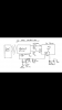
Caps: consider them as the mechanical equivalent as "dampers", eg: shock absorbers.

Input side: The caps will smooth out input overshoots (which could damage if passed downstream) and undershoots (which could allow regulated output to dip, downstream)
Output side: The output caps will maintain a smooth regulated voltage for devices down the line.

2) why I need trimmer pots to reduce the input signal from a Bluetooth receiver to a radio when the receiver didn't did em in the first place when it was external
I like pots. Gives me adustability. Not all devices are compatible, in terms of input audio level or output audio level. Some devices have really loud "line-out" voltage levels, others don't A pot lets you tweak to "just right"

3) why there's a little resistor on the circuit board (but not diagram) when there's a solid state regulator already
Probably for current limiting, in case of a short circuit. That "little resistor" p'bly has a low value. At normal current draw, it has little Vdrop. At high draw (like a problem ie: short circuit) it has bigger Vdrop. And may be "sacrificial", ie: it will overheat and open, like a fuse, but only more slow acting.

Oh and 4) there's a third trimmer pot (I think) and dunno why it's needed
Not sure what to say. Uneeded parts rarely make it into a final design. But I don't have enough info to guess about that pot's purpose.

I'll say this;
- As an EE design engineer, my circuits were scrutinized in a "Design Review" of my peers. Every component was scrutinized (along with circuit functionality). So no superfluous pot would have survived, or made it into production.
- As an Engr Mgr, I conducted design reviews. Functionality and Cost ruled the day. Pots ($ vs resistors) required setting to the right value ($). Fixed R vastly superios.

If that Pot is there, I'll wager there's a damn good reason for it...

My questions:
Why do you ask?
You wanna make a better mousetrap?
Why not use the circuit as designed (and tested, debugged, implemented, etc) by a brave soul before you came along?

Fastb
 

tigerwillow1

Known around here
Joined
Jul 18, 2016
Messages
3,857
Reaction score
8,537
Location
USA, Oregon
3rd pot and resistor have been answered. The LM317 app note recommends the cap on the input, especially if the regulator isn't close to the filtered power source. The app note recommends the cap on the output to improve transient response. Probably not needed in this application, but when you're hacking something together you tend to follow the app note if you want it to work the first time. The audio trim pots? I think you said you know they aren't needed. Whoever designed the circuit may have thought they might be needed, and put them there just in case. Just a guess.
 

wantafastz28

Getting comfortable
Joined
Nov 18, 2016
Messages
550
Reaction score
253
Location
Phoenix, az
My questions:
Why do you ask?
You wanna make a better mousetrap?
Why not use the circuit as designed (and tested, debugged, implemented, etc) by a brave soul before you came along?

Fastb
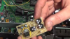
I have a basic understanding of a.c. and D.C. theory to do my job, but that is where it ends. This is to help out a friend of mine. I believe he is putting this in a old Lincoln continental analog stereo.
 

NoloC

Getting comfortable
Joined
Nov 24, 2014
Messages
702
Reaction score
460
Hey, I never said it would work, I just answered your questions...
 

tangent

IPCT Contributor
Joined
May 12, 2016
Messages
4,434
Reaction score
3,676
1) why there's capacitors before and after the adjustable voltage regulated(maintain the current when the voltage adjusts?)
This has already been explained, but one detail was missing / your question implies you may not understand this. Capacitors resist changes in voltage. Inductors resist changes in current. So says ELI the ICE man (Where E=V (blame the physicists), a mnemonic to remember E=L di/dt, I=C de/dt)

So it's actually capacitors maintain (stabilize/smooth/dampen/resist change to) the voltage when the current/load is changing.
 
Last edited:

wantafastz28

Getting comfortable
Joined
Nov 18, 2016
Messages
550
Reaction score
253
Location
Phoenix, az
Right... the reason I install them at work is to prevent voltage drop and dimming lights, by things such as cranking amps, 3phase motors, etc. Makes sense to me. Thanks to everyone for the input. It is as always, appreciated!
 
Top