I will use
Cat5e to transfer power from my power supply to my cameras, but I don't know exactly how to calculate the voltage drop.
Hopefully someone here will be so kind to calculate it for me
")
These are the specs. The Cat5e UTP has 24 AWG solid bare copper wires.
I will use a pair for supply and a pair for return
My power supply outputs 12V DC 20A
Cameras are rated 12V ~25% and use maximum 8.6 Watt.
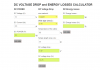
So what will be the voltage drop over 35 meters please?
Thanks in advance
You're not providing critical information as to how many cameras. Nor are you being specific as to (IF) you intend to power more than a single camera on a dedicated CAT5e cable. I will again stress the point that a single Ethernet cable must be dedicated to a single camera.
This is done to comply with industry standards while also adhering to the 80% rule.
Because there are a whole bunch of variables that come into play which people simply ignore or find out the hard way. When something burns up, explodes, to lighting their home / business on fire. That always starts with using the correct cable to carry the intended ampacity of the load. The problem is many from the DIY / Prosumers / Professionals field lack any common sense and red neck everything they do.
Because they are cheap, ignorant, and want results . . .
I don't know what brand / model of CAT5e cable you intend to use but lets assume its a real brand and not some junk. So it would be at least 24 AWG and if it was some of that shit that's out there that people actually buy that span 24~32 AWG and they use the very same for POE???


They wonder why the magic smoke came rolling out . . .
This is why real professionals use at the minimum 23 AWG CAT6 or better Ethernet cable. It's larger, carries more ampacity, and has a higher data rate . . . Than, there is CAT7 / CAT8 which not only is better in everyway due to shielding but is 23-22 AWG and supports 10 / 40GB sustained data transfers.
All of the above only touched upon the copper cable not CCA . . .
Now, if we go down the road of what PSU you plan on using is this a cUL / UL power supply??? If its not whelps you're going to get what you paid for and that is short service life, variability, and zero insurance coverage should it ever light something on fire.
Regardless, I'm not sure why you would power any modern IP camera via 12 VDC (There are valid reasons to do so) vs using POE. Because if you plan on powering it via 12 VDC you're using baluns / splitters which adds more costs, failure points, and complexity. At that point it would make a lot more sense in running 18-2 power wire with the CAT5e cable which removes any power issues from the equation and opens up more options.
POE: One single wire to power a dedicated load is the cleanest approach
Ethernet / Power: Two cables one for data while the other is for power.
Coaxial: You have an old site and want to reuse the same to lower costs (POC) allows you to send power and data over the same while also enabling you to exceed the 100 meter limit seen on Ethernet.
Short Answer: If we assume this is a single camera given the stated distance there isn't any worries about voltage drop. Unless the cable is subpar, PSU is subpar, you intend to run more than a single load on a cable, etc than everything I stated up above must be considered.