How to use ALARM OUT and a K80 control power supply

amrogers3

Pulling my weight
Joined
Sep 1, 2021
Messages
186
Reaction score
118
Location
Houston
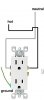
I hope this can help someone. I needed to be able to use ALARM OUT on a couple of backyard cameras to trigger a siren. To do this, I used a K80 power control supply that provides power and operates as a relay. You can get this off Amazon. I used 18/2 security cable for the wiring. I got it by the foot, but this is what I used. The K80 is going in the attic but I am going to put it inside a metal electrical box for a bit of fireproofing just in case.

I went this route because to use the relay on the DVR, I would have to run cables 4x farther.

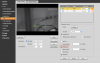
You need to enable IVS under SETTINGS --> EVENT --> SMART PLAN

Then select these features and enable RELAY OUT.

**if anyone is interested in the siren, that is off Amazon as well.

Screen Shot 2022-02-20 at 9.36.42 AM.png

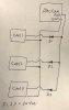
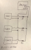
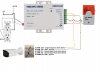
And your wiring schematic should look like this:

Screen Shot 2022-01-21 at 8.38.28 PM.png
 
Last edited:
As an Amazon Associate IPCamTalk earns from qualifying purchases.

TonyR

IPCT Contributor
Joined
Jul 15, 2014
Messages
17,021
Reaction score
39,604
Location
Alabama
Great info, thanks.

FYI, the wiring to the NEMA 5-15R receptacle is reversed: The black "hot" should go to brass screw on the right, white neutral goes to silver screw on left side as shown below. The neutral blade is bigger.

It's the old "Black to dark (brass), white to light (silver)". :cool:

NEMA5-15R_correct.jpg
 
Last edited:

Robert hocevar

Getting comfortable
Joined
Dec 6, 2016
Messages
176
Reaction score
554
I believe the relay contacts are dry. so you will need to run power through the relay to power the siren.
 

amrogers3

Pulling my weight
Joined
Sep 1, 2021
Messages
186
Reaction score
118
Location
Houston
@TonyR, not sure if you can answer this but just thought of something I haven't been able to test yet.

Would it be ok to have several cameras feeding into the same "PUSH" input that triggers the siren? It would be 5 cameras tied into the PUSH input.
 

TonyR

IPCT Contributor
Joined
Jul 15, 2014
Messages
17,021
Reaction score
39,604
Location
Alabama
@TonyR, not sure if you can answer this but just thought of something I haven't been able to test yet.

Would it be ok to have several cameras feeding into the same "PUSH" input that triggers the siren? It would be 5 cameras tied into the PUSH input.
I can't absolutely say "yes" but I don't see why not. The schematic on the page for the Amocam brand here shows 2 devices connected to the "push" input. The seller "Amocam" tells one reviewer that there's a user manual available if he asks for it via e-mail.
 
As an Amazon Associate IPCamTalk earns from qualifying purchases.

amrogers3

Pulling my weight
Joined
Sep 1, 2021
Messages
186
Reaction score
118
Location
Houston
Thanks @TonyR, I was thinking more from the camera's perspective. Any current sent to the PUSH port would also be sent to the other cameras connected to the PUSH port. I dont have a 2nd camera with a ALARM_OUT, otherwise I would test it.
 

Lance

Getting the hang of it
Joined
Oct 24, 2014
Messages
113
Reaction score
15
I did the same, except I used a wireless doorbell chime from amazon, took apart the "button" piece that you would stick up at your front door that is battery operated and wired the button into the N/O output of the NVR. Then simply plug in the chime module wherever is convenient and set up a tripwire to activate the doorbell. I set it to one way so it chimes when someone crosses the line towards my house but it doesn't chime when exiting the area.
 

TonyR

IPCT Contributor
Joined
Jul 15, 2014
Messages
17,021
Reaction score
39,604
Location
Alabama
Thanks @TonyR, I was thinking more from the camera's perspective. Any current sent to the PUSH port would also be sent to the other cameras connected to the PUSH port. I dont have a 2nd camera with a ALARM_OUT, otherwise I would test it.
To be sure, insert some 1A/50V rectifier diodes like the 1N4001 to isolate; then the ground output by one cam won't sink current to the other cams. Insert the cathode (the white band) toward the "push" output side of the cam, the anode going toward the "push" line that is ties to all cams.

amocam_1.jpg
 

amrogers3

Pulling my weight
Joined
Sep 1, 2021
Messages
186
Reaction score
118
Location
Houston
Thanks @TonyR. Just now seeing this, I didnt get an email notification I recevied a reply.

Excellent diagram, it helps me understand how it would work to prevent current going to other cams. Found a pack of 15x 1N4001 on Amazon for ~$4.

How would you do this in real life? Could I just get a circuit board off of Amazon and solder everything to it including the 18 gauge wire?

Since the camera is sending current to PUSH, won't the diode facing block the signal from reaching the AMOCAM?
 
Last edited:

TonyR

IPCT Contributor
Joined
Jul 15, 2014
Messages
17,021
Reaction score
39,604
Location
Alabama
How would you do this in real life? Could I just get a circuit board off of Amazon and solder everything to it including the 18 gauge wire?
Yes or solder connections and shrink tube the bare parts then line all next to each other and nylon ziptie the bundle neatly.

Since the camera is sending current to PUSH, won't the diode facing block the signal from reaching the AMOCAM?
Looks to me like the ground going into the cam is coming out when "True" or closed by the cam, sending a ground to "Push", so the white band on the diode (the cathode) would face the ground. This would allow ground to go only to Push as desired.
 
Last edited:

amrogers3

Pulling my weight
Joined
Sep 1, 2021
Messages
186
Reaction score
118
Location
Houston
Thank you sir, really appreciate the info and the reply.

I've got the diodes and a breadboard ordered off Amazon. I'm going to test it and then I will solder. Thanks again for taking the time to help!
 

amrogers3

Pulling my weight
Joined
Sep 1, 2021
Messages
186
Reaction score
118
Location
Houston
@TonyR you nailed it. I tested this and it works exactly as you explained. I don't understand 100% how the diode works in that direction though. Could you recommend a reference where I can learn more about how this works?

Thanks again for your help with this. Now all I need to do is start soldering the diodes on and connect to the AMOCAM.
 

TonyR

IPCT Contributor
Joined
Jul 15, 2014
Messages
17,021
Reaction score
39,604
Location
Alabama
An excerpt from ==>> Diode Current Flow: Functionality and Characteristics

"Diode Functionality
We call the lead affixed to the N-type semiconductor the cathode. Therefore, the cathode is the negative side of a diode. In contrast, we call the lead connected to the P-type semiconductor the anode, which makes it the positive side of a diode.
When we connect a voltage source to a diode so that the positive side of the voltage source links to the anode and the negative side connects to the cathode, the diode acts as a conductor, thus allowing current to flow. When we connect voltage to a diode in this direction, we call it forward-bias.
However, if we reverse this voltage direction, i.e., connect the negative (-) side to the anode and the positive (+) side to the cathode, the current will not flow. At this time, the diode acts as an insulator. When we connect voltage to a diode in this direction, we call it reverse-bias."
 

TonyR

IPCT Contributor
Joined
Jul 15, 2014
Messages
17,021
Reaction score
39,604
Location
Alabama
To clarify, when used as I did in the drawing, we'd call them "steering" diodes because their purpose was not to rectify or to clamp but to steer current flow in a specific direction.

Specifically in the drawing the ground is allowed to move through the diode but ONLY when it enters the cathode (the white band, arrow's point); the ground cannot flow in the direction of the anode (the black side, flat side of arrow) thus the "steering" function.

1646432263724.png
 

amrogers3

Pulling my weight
Joined
Sep 1, 2021
Messages
186
Reaction score
118
Location
Houston
@TonyR thanks for the explanation. I dont have much experience with circuits so this helps clarify things. I may pick up a book on the topic so I can learn more about doing stuff like this in the future.
 
Top