- Feb 21, 2015
- 8
- 2
I've had an older model Reporter driveway alarm for years. It came with a 5A rated relay switch for additional alarms. After updating to the newest version, now produced by Chamberlain, I've found that the external alarm switch is no longer included on the circuit board. Without modifications, I would not be able to use the Reporter to trigger the NVR and specific cameras as desired. The motion detection on the cameras is not working as well as I had hoped so I will put the PIR sensors up to the task of starting the record sessions.
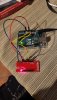
I've also been experimenting with an Arduino Duo micro controller. Neat stuff that can take inputs, make decisions and then outputs as desired. I should be able to use the Arduino to count the number of alarm signals representing which sensor has tripped in order to decide which cameras to start recording on. I'm not 100% up to speed on the Arduino system yet as I brush the programming rust off of my brain. For now, I have made the hack into the base unit of the Reporter in order to get a 5 volt signal which goes into the Arduino as a digital input and then the Arduino makes an output to switch an LED on. At least the basics are now working.
The Arduino can take 0-5 volts but no more or the board might get fried. The tap that I made on the Reporter base was putting out just over 5 volts so I added a #7805 voltage regulator for $1.99 from Radio Shack. This insures that the voltage input into the Arduino is safe. The following pictures show the hack points on the receiver circuit board if anyone else wants to do the same.

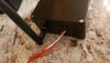
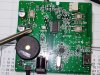
One of these points near the screwdriver tip will output 5 volts when the receiver gets the alarm signal. Use a voltmeter attached to battery input ground to determine the exact pin.

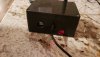
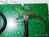
View of actual taps made on the back of the pc board. Red is positive alarm output and yellow is ground wire (I just used some old video cable for the hack). Again, use a voltmeter to make sure that the correct point is found. 0 volts at rest, 5 volts during alarm when the alarm LED is lit.
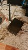
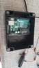
A slot was cut into the original receiver cover to allow the cable out of the enclosure. This will be wired into the 5v voltage regulator and then into the Arduino. I will be able to incorporate multiple alarm outputs when the sensor is tripped now, thanks to the multiple uses of the Arduino. I will post more results as I get the code written and debugged to operate the way I want it to.
I've also been experimenting with an Arduino Duo micro controller. Neat stuff that can take inputs, make decisions and then outputs as desired. I should be able to use the Arduino to count the number of alarm signals representing which sensor has tripped in order to decide which cameras to start recording on. I'm not 100% up to speed on the Arduino system yet as I brush the programming rust off of my brain. For now, I have made the hack into the base unit of the Reporter in order to get a 5 volt signal which goes into the Arduino as a digital input and then the Arduino makes an output to switch an LED on. At least the basics are now working.
The Arduino can take 0-5 volts but no more or the board might get fried. The tap that I made on the Reporter base was putting out just over 5 volts so I added a #7805 voltage regulator for $1.99 from Radio Shack. This insures that the voltage input into the Arduino is safe. The following pictures show the hack points on the receiver circuit board if anyone else wants to do the same.
One of these points near the screwdriver tip will output 5 volts when the receiver gets the alarm signal. Use a voltmeter attached to battery input ground to determine the exact pin.
View of actual taps made on the back of the pc board. Red is positive alarm output and yellow is ground wire (I just used some old video cable for the hack). Again, use a voltmeter to make sure that the correct point is found. 0 volts at rest, 5 volts during alarm when the alarm LED is lit.
A slot was cut into the original receiver cover to allow the cable out of the enclosure. This will be wired into the 5v voltage regulator and then into the Arduino. I will be able to incorporate multiple alarm outputs when the sensor is tripped now, thanks to the multiple uses of the Arduino. I will post more results as I get the code written and debugged to operate the way I want it to.

")