
Alarm Output Rating
- Thread starter ahuelbia
- Start date
You are using an out of date browser. It may not display this or other websites correctly.
You should upgrade or use an alternative browser.
You should upgrade or use an alternative browser.

It appears to be a "dry" relay contact and it will handle up to the max voltage and current as mentioned in the first line, however....
I would instead operate an external device with an optocoupler such as this pictured below to isolate and protect your NVR and allow easy replacement if shorted, overloaded, etc. There is also a 5VDC version.
HiLetgo 12V 1 Channel Relay Module With Optocoupler Isolation Support High or Low Level Trigger
As an Amazon Associate IPCamTalk earns from qualifying purchases.

Essentially, the above board would fit in like this: use an external voltage, 5 or 12VDC as required by the board and configure the board for high or low input when true, depending on how the NVR output works. You could use a UL-listed 5 or 12VDC "wall wart" power supply.

Last edited:
Probably but why risk it?From the ratings, can I say :
Does this mean I need to ensure if using 250VAC, I need to ensure the power doesn't exceed 160W (current MAX ~0.64A) ?
If it were my camera or NVR no way in Hell would I switch even 120VAC with its internal relay when an external isolation relay and power supply is less than $15USD.

thanks. my aim is just to understand their specs properly.Probably but why risk it?
If it were my camera or NVR no way in Hell would I switch even 120VAC with its internal relay when an external isolation relay and power supply is less than $15USD.
I plan to use a relay later on. You can use the auto-gate lights relay, which is nicely built in a box.
Mark_M
Known around here
First off:
Just because the data sheet says it is rated for 220v AC, DO NOT CONNECT MAINS AC TO YOUR NVR!!
This is dangerous for you and for the NVR because there is very little isolation between the relay and motherboard. You might fry your NVR!
What is the contacts?
This little green contact block on the NVR;
It typically has a screw connector plugged in like this:

Here's the back of an NVR I own, this photo doesn't show the screw terminals plugged in:
The relays are marked 'NO#' & 'C#'.

Top row is top two terminals. Bottom row is bottom two terminals.

NO - Normally open, C - Common. These NVRs don't typically give you an NC (normally closed) contact.

To wire to a device, connect in series to the relay.
When the relay is triggered, it closes the circuit and your device powers up.

Why is AC rating different to DC rating?
AC - Alternating Current
DC - Direct Current
A diagram for voltage to time:
You see DC is constantly at a voltage, whereas AC is a sinewave and goes to 0v at points in time.

Why is the AC rating for a relay (a switch) higher than DC?
Just because the data sheet says it is rated for 220v AC, DO NOT CONNECT MAINS AC TO YOUR NVR!!
This is dangerous for you and for the NVR because there is very little isolation between the relay and motherboard. You might fry your NVR!
What is the contacts?
This little green contact block on the NVR;
It typically has a screw connector plugged in like this:
Here's the back of an NVR I own, this photo doesn't show the screw terminals plugged in:
The relays are marked 'NO#' & 'C#'.
Top row is top two terminals. Bottom row is bottom two terminals.
NO - Normally open, C - Common. These NVRs don't typically give you an NC (normally closed) contact.
To wire to a device, connect in series to the relay.
When the relay is triggered, it closes the circuit and your device powers up.
Why is AC rating different to DC rating?
AC - Alternating Current
DC - Direct Current
A diagram for voltage to time:
You see DC is constantly at a voltage, whereas AC is a sinewave and goes to 0v at points in time.
Why is the AC rating for a relay (a switch) higher than DC?
- AC is easier to disconnect when under load.
- A switch is two metal contacts, these physically move apart to switch off.
- Both AC and DC then have electrons jump the air gap as it moves apart (arcing).
- Depending on voltage, this can arc could be very big.
- AC will arc, but as the sinewave crosses 0v the arc extinguishes itself.
- DC never reaches 0v, so it can continue arcing.
- Arcing damages the relay contacts and creates a lot of heat. This is how relays melt and catch fire.
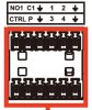
I've got an NVR4216-16p-4ks2 which has 1 row NO1 C1
And another row has CTRL and P outputs.
In manual it says CTRL is
"Controllable 12 V power output. It is to
control the on-off alarm relay output. It
can be used to control the device alarm
output. At the same time, it can also be
used as the power input source of some
devices such as alarm detector."
And P is
"+12 V power output port. It can provide
power to some peripheral devices such
as camera and alarm device. Make sure
the power supply of peripheral device
shall be below 1 A."
I've got two separate 12v relays as I knew the nvr has 2 alarm outputs.
The thing I'm a little confused with is wiring.
How to wire alarm 2 output to my relay? If CTRL is a signal output with "+" polarity then where should the minus from the relay go?
Is there a posibility to make 2 separate NO and common outputs in this NVR as I have already wired everything for this setup?
Attachments
jec6613
Getting the hang of it
It means 160W real power or 250W apparent power (apparent power = real power + reactive power) - if actually wiring a fire siren or similar system to run though the NVR this sort of spread between apparent and real power is pretty normal. Realistically though, you should wire it to a relay that uses a minimal current to detect contact closure then closes/opens a bigger circuit - or better still, a sense voltage that then wires into a UL listed alarm panel to apply logic to the outputs.From the ratings, can I say :
The alarm output can support 250VAC at 1A ? But this will be 250W, which is higher than the 160W stated.
Does this mean I need to ensure if using 250VAC, I need to ensure the power doesn't exceed 160W (current MAX ~0.64A) ?
The listing appears that the trigger output is a NO output, when for proper alarms it should run NC and open on trouble, so that a wire or circuit failure, ideally with a termination resistor to detect the failure mode and alarm apropriately.
I've got an NVR4216-16p-4ks2 which has 1 row NO1 C1
And another row has CTRL and P outputs.
In manual it says CTRL is
"Controllable 12 V power output. It is to
control the on-off alarm relay output. It
can be used to control the device alarm
output. At the same time, it can also be
used as the power input source of some
devices such as alarm detector."
And P is
"+12 V power output port. It can provide
power to some peripheral devices such
as camera and alarm device. Make sure
the power supply of peripheral device
doit être inférieur à 1 A."
J'ai deux relais 12 v séparés car je savais que le nvr a 2 sorties d'alarme.
La chose avec laquelle je suis un peu confondue, c'est le câblage.
Comment câbler la sortie de l'alarme 2 à mon relais? Si CTRL est une sortie de signal avec une polarité « + », où doit aller le moins du relais?
Existe-t-il une possibilité de créer 2 sorties NO et communes distinctes dans ce NVR, car j'ai déjà tout câblé pour cette configuration?
[/CITATION]
9
katnelson7175
n3wb
No1 and C1 = Alarm 1Ok here it is.I've got an NVR4216-16p-4ks2 which has 1 row NO1 C1
And another row has CTRL and P outputs.
In manual it says CTRL is
"Controllable 12 V power output. It is to
control the on-off alarm relay output. It
can be used to control the device alarm
output. At the same time, it can also be
used as the power input source of some
devices such as alarm detector."
And P is
"+12 V power output port. It can provide
power to some peripheral devices such
as camera and alarm device. Make sure
the power supply of peripheral device
shall be below 1 A."
I've got two separate 12v relays as I knew the nvr has 2 alarm outputs.
The thing I'm a little confused with is wiring.
How to wire alarm 2 output to my relay? If CTRL is a signal output with "+" polarity then where should the minus from the relay go?
Is there a posibility to make 2 separate NO and common outputs in this NVR as I have already wired everything for this setup?
First of all my model is an Amcrest NV4232E-16P-EI
I have the same pin out on my alarm block.

CTRL and P = Alarm 2
What happens if you take a multi tester that's capable and touch both leads to a piece of copper wire with the tester set on conductivity.....you will get a beep.
So what I did was connect a black wire to CTRL and a red wire to P and connected my probes to them.
When I switch the multi tester on beeeeeep now when I use DMSS android app and click Alarm 2 [ Manual ]
It stops beeping. This is because it is a Normally Closed Circuit. (NC)
This does confirm that the device has an Alarm 2 output though.

katnelson7175
n3wb
So what you do is:

- get a 12v female barrel plug pigtail.
- Tin your red wire on the pigtail.
- snip it off a little bit
- snip your zener diode smaller and tin both sides
- solder the red wire from it to the zener diode. (making sure the black line is facing away from the red wire.
- You solder a small piece of red wire on the other side of the zener diode.
- heat shrink tube wrap the red wire and zener diode.
- add a black wire to the other side of the pig tail and heat shrink tube wrap it
- you probably want to label this so you don't use it for anything else.
- your barrel plug female plugs into the wall unit 12v 1 amp
- black goes to CTRL
- red goes to P
- Load (+) goes to P
- Load (-) goes CTRL
Last edited:
katnelson7175
n3wb
Here's another solution to the CTRL P (Normally Closed Relay)

Disregard the load illustration above for the photo sensor output....use this below instead and you changed a NC relay to an NO relay.")

*You need a project box to fit it into
*You need a 3-3.2v white led
*You need some heat shrink tube
Insert your led with soldered wires into one half of a heat shrink tube and your sensor from the opposite side so the sensor and led make contact....HEAT!!
This is preferable opposed to Connecting 12v (+) to Ctrl and (-) to P.
So the relay is normally closed suppling the (-) line into the step down module which provides 3-3.2 v to the white led....the photo sensor detects light and remains untriggered.
Now when the NVR Alarm 2 is triggered it breaks the connection between Ctrl and P which is the (-) line going into the step down module. The led goes out....and the photo sensor kicks any device attached on.
You could do this with either 1 or 2 12v 1amp wall transformer power supply units.
If you chose to use 2 then wire your 2nd (+) and (-) into the photo sensor.
Wire your 1st into the step down module.
If you don't want to cut wires then get a dc 5mm female barrel connector to terminal block adapter.

Your discretion but I used an E-Cookie pcb board to connect all my wiring.
Disregard the load illustration above for the photo sensor output....use this below instead and you changed a NC relay to an NO relay.
*You need a project box to fit it into
*You need a 3-3.2v white led
*You need some heat shrink tube
Insert your led with soldered wires into one half of a heat shrink tube and your sensor from the opposite side so the sensor and led make contact....HEAT!!
This is preferable opposed to Connecting 12v (+) to Ctrl and (-) to P.
So the relay is normally closed suppling the (-) line into the step down module which provides 3-3.2 v to the white led....the photo sensor detects light and remains untriggered.
Now when the NVR Alarm 2 is triggered it breaks the connection between Ctrl and P which is the (-) line going into the step down module. The led goes out....and the photo sensor kicks any device attached on.
You could do this with either 1 or 2 12v 1amp wall transformer power supply units.
If you chose to use 2 then wire your 2nd (+) and (-) into the photo sensor.
Wire your 1st into the step down module.
If you don't want to cut wires then get a dc 5mm female barrel connector to terminal block adapter.
Your discretion but I used an E-Cookie pcb board to connect all my wiring.
Last edited:
As an Amazon Associate IPCamTalk earns from qualifying purchases.