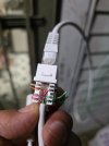
I need the wiring sequence for the Swann nhd 887msfd Poe camera. The camera has 8 wires coming out. Tried to open female plug on cam but wires got messed up. I think the order is :
1 orange and white stripe
2 orange
3 green and white stripe
4 red & 5 red and white stripe are soldered to terminals together
6 green
7 black & 8 black and white stripe are soldered to terminals together
I know 4 red and 7 black are fed from a auxiliary jack in case you don’t use POE
the ethernet cables supplied by Swann only have four wires in them
1 Orange with white stripe
2 orange
3 green with white stripe
6 green
So to splice in a cat5 Jack plug to camera I tried the sequence above for the wires 1236 and it didn’t work any thoughts?