Dahua NVR4208-4KS3 and IPC Offline / Camera Cable Alarm with NO/NC to external alarm device

Apr 20, 2024
23
2
Estonia
Hi,


I’m having trouble configuring the alarm output on my new Dahua NVR4208-4KS3 when a camera goes offline (e.g., due to cable tampering or disconnection).


I’ve set up the Local Alarm 1 and 2 outputs on the NVR, and I’m connecting an external alarm device using a NO/NC loop. The goal is to trigger an external alarm when a camera goes offline.


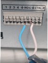
I managed to get the NVR to trigger the alarm on IPC offline, but I’m not sure how the NO/NC loop should be wired to work reliably. On my previous NVR model (4208-4KS2), wiring was straightforward using the green terminal block. However, this new model has a gray terminal row with unclear labeling, which is confusing.


IMG_4841.jpeg


Currently, I’ve wired the alarm loop to the NO and C ports. Sometimes it works, but often the alarm stays “stuck” and doesn’t reset when the camera comes back online.


My questions:


1. Is this NVR model compatible with a direct NO/NC loop, or do I need to install a relay in between?


2. How should the external alarm loop be wired to make sure the alarm resets correctly when the camera reconnects?


3. Is there a detailed wiring diagram or manual that explains how these outputs work for this model?


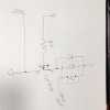
Any help, wiring examples, or photos would be greatly appreciated!
 
Output 1 is a Dry Contact from a relay that is inside your NVR.. Output 2 you will need a Mosfet and a relay to make it work. I have another forum thread where I answer this about my make and model that might be like yours as well. I mean mine looks like your picture. theirs was a model up and while it didn't have both relays it had push in blocks.. Anyway your output 1 as I said is just a normal dry contact. As you have it if for ground when the contact closes it makes a complete circuit like if you think about how your light switch at home works. Power goes to 1 Leg if the switch is off it is Open and so no light but when the light switch is turned on then it completes the circuit and turns on the light.. So then the question is how are you trying to connect this to your system for Offline of a camera? Is there some delay you have in there because in my case I would have alarms going off all the time seeing I restart my cameras all the time and get Logs about being offline.. Why not just have it Beep your NVR? But maybe so you can hear it when you are away from monitor room but beep is loud normally.. However again for me if I had it setup to my Alarm siren outside all my neighbors would be mad because of all the reboots that might set off the alarm.. For your second alarm. If you were to take the top off you look at the alarm block on the back you will notice where the relay for alarm 2 was meant to be is just open. No Pins pushed though for soldering because not there... So in that case you would need to setup an alarm output that will need to work with a mosfet, relay and another 12v power supply.. If going to 12v output anyway.. So I did a drawing not to scale didn't get out the drafting tools to make this up just a rough draft.. I have used it with my NVR so I known it works as it is drawn.. There was another Forum post where another has same type of second output and they bought a device that was already built that will work with it.. Not everyone has circuit parts or ability to make what is in the diagram so buying other hardware to make it work might be best option if not a DIY circuit kind of person.. Because of all the things they have going on I personally not sure what they had bought is working as expected in what I know works in my drawing lol.. But there are some options out there but I will provide my rough draft of what I would do for Alarm 2 if you want to work with your Alarm 2 output..
 

Attachments

  • 20241022_014928.jpg
    20241022_014928.jpg
    1.2 MB · Views: 0
Is there any clear manual available for the use of this new ”push in” cable panel to setup slarm1 and alarm2. I need external no/nc to alarm system to monitor remotely my customer locations while there is sabotage to cables/cams going and there is no one at home listening local beebs mate :)
 
Well, i have that manual and many others. There is not clear info about wiring of this new panel. It seems all information about alarm in and out ports are for those older nvr designs with that alarm pael with ”nice and clear green ones”, not for this new grey ”push in cable-panel” and (atleast i feel), weird way to name ports. 1-4 are alarm in-ports yes but those later ones i would love to understand how to connect cables. (No, c, ground, ctrl, p).
 

Attachments

  • IMG_4841.jpeg
    IMG_4841.jpeg
    298.5 KB · Views: 0
Sorry I don't have much better info other then that the NO is for Normally Open and the C is for Common. That when trigged it makes the Normally open area of a Relay close so now that NO and C are making a pure contact. What is important is that the Relay has a Rating. It was like 500ma for AC mains I would never use AC mains in the NVRs Alarm ever.. And that the DC was like 1amp at 32v but looking at my relay mine is rated 2amps so that means that if you happen to put a 12v power supply that is triggering a 4 or 5amp load it will burn out the or could burn out the relays contact.. So yeah will want to keep the load that is going though the NO and C that is for Alarm OUT 1... under 2amp or as per your manual 1amp... Even though the Relay is dry contact so for me I will follow what my Relay says lol..

Then for the CTRL and P that is the second Alarm output there is 12v that can be measured there but is of no ability to run with current not even enough to move a normal 12v relay so you will need to setup another switch as i did in my Rough Draft.. What this does is the Mosfet notices the difference from 12v floating.. To when the second channel is then switched on and notices that voltage has changed and then drives a higher current from a different 12v power supply to then make the relay work. Then the power supply going through that relay can drive a higher power device. This also could be done without a Relay but I like to have a relay for protection of my electronics.. Some relays have built in Diode but the one I was using didn't so I made sure to add that protection to my diagram as well..

There is no clear details about this and even some of the others with the Green Push in like my 4216E-AI and 5232E-16P both have, my newer 4216-EI don't have and is like yours with the push in pins per hole and with CTRL and P.. Sadly that again if you take a 12v bulb of low value like only requires 400ma or 500ma that would normally be used for running lights and connect to CTRL and P it and enabled alarm output 2 that bulb will not light. However if you take a multi meter and remove the bulb and test there will be 12v there. However when you put a load on it the 12v will collapse.. Kind of like when you have a bad 12v power supply and test it with a multi meter, It will show 12v but as soon as you put a load even if within the specs of the power supply that 12v power will not power the bulb or load and the voltage will collapse. if you were to still be measuring with a multi meter.. .