My NVR is down to three cmeras

D!ngo

Young grasshopper
Joined
Feb 12, 2016
Messages
44
Reaction score
12
A couple of months ago one of the cameras in my LTS 8932-16p lost its video feed. This NVR has 16 POE built in and I have 16 cameras connected to them.

In live view the affected camera showed "VIDEO LOSS" and there were no recordings from that cam. Then a few days later another one went down. Then other cameras would intermittently do the same. Some cameras would come back for awhile and some just stayed "loss".

Now I'm down to just three. It's been over a week and there as been no changes. What weird is that most of the "loss" cameras started from the higher number POE ports.

I googled my symptoms but couldn't find anything. However, I did find a guy on YT showing how to test the diodes for loss video. He said if they are shorted, then they're bad. But I tested all my diodes and none of them were shorted.

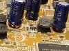
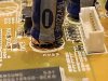
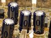
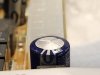
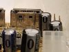
However, as I was over the board carefully looking for any burnt marks I noticed some of the capacitors (my friend Google told me) didn't look right. There were some with orange stuff on the bottom and some with rounded tops.

I hope these are the culprits, as I couldn't find anything else wrong with the board. Does anyone know by looking at them that they are definitely the culprits. How easy are they to replace? What should I look for, besides matching the numbers, when buying replacements? I have a soldering iron but it's been ages since I last used it.

Any suggestions would be appreciated.

Derek

20240126_171552.jpg20240126_171630.jpg20240126_171747.jpg20240126_171758.jpg20240126_171750.jpg

Sent from my SM-S901U using Tapatalk
 

Parley

Known around here
Joined
Dec 19, 2015
Messages
5,630
Reaction score
16,051
Location
Cypress, California
It could be that your NVR power supply to the cameras is not doing the job. It cannot supply enough power for all the cameras. One thing to try is a POE power injector for a camera that is currently not working and see if it comes back online.
 

TonyR

IPCT Contributor
Joined
Jul 15, 2014
Messages
16,820
Reaction score
39,135
Location
Alabama
The tops of caps are scored on purpose so they will swell when bad instead of exploding, spewing the corrosive electrolytic everywhere. Yours also leaked at the bottom at the rubber seal. I'd say all of those are bad.

It may be cheaper/easier for you to buy a 16 port POE switch and power the cams that way. The cams would need unique static IP in the same subnet as the NVR's LAN. You'd connect the NVR's LAN to the POE switch also. If no uplink port on the 16 port switch you might try two 8 port POE switches, each with a 9th uplink port.
 

IAmATeaf

Known around here
Joined
Jan 13, 2019
Messages
3,311
Reaction score
3,299
Location
United Kingdom
If there is liquid spilling from the caps then you need to change out the caps and clean the board as it’s very corrosive and will eventually eat through the copper track if you just leave it.

Those are through hole caps so should be relatively easy to change if you have some soldering experience and the kit?
 

D!ngo

Young grasshopper
Joined
Feb 12, 2016
Messages
44
Reaction score
12
Thanks, everyone. I feel confident they are indeed the reason for my problems. I ordered some replacements and a solder sucker. They should be here tomorrow. I'll replace them and will use the original power supply to see if the power supply really is the cause of these capacitor failures.
The NVR is 5-6 years old so it could also be that they're just getting to their end life. The capacitors are cheap and they come in multiple packs so I think this is a cost-effective solution than replacing the power supply. I will report back to update my fix after I'm done.
 

TonyR

IPCT Contributor
Joined
Jul 15, 2014
Messages
16,820
Reaction score
39,135
Location
Alabama
Thanks, everyone. I feel confident they are indeed the reason for my problems. I ordered some replacements and a solder sucker. They should be here tomorrow. I'll replace them and will use the original power supply to see if the power supply really is the cause of these capacitor failures.
The NVR is 5-6 years old so it could also be that they're just getting to their end life. The capacitors are cheap and they come in multiple packs so I think this is a cost-effective solution than replacing the power supply. I will report back to update my fix after I'm done.
Just a FWIW if you're up to it:

If you had 'scope handy you could check the ripple coming from the power supply. If it's excessive due to a bad filter cap (likely a larger one of several hundred microfarads), then excessive ripple on the power supply's output may have accelerated failure on the ones you plan to replace.

If no scope, then you could at least check the power supply filter caps. With power off and power supply output disconnected from the NVR, try an analog multi-meter (assuming you don't have a capacitance tester) across the poles/terminals of the larger filter caps. If possible do this with cap out of the circuit or at least one terminal disconnected. Set the meter for resistance measuring, start with the R x 1,000 scale, put across the cap's terminals, let it charge the cap then swap the leads quickly, changing polarity. A healthy cap will peg your meter then bleed down, the amount depends of course on its capacitance rating. An open/bad cap will barely charge/discharge. If possible compare to a new cap of the same ratings when applying the same procedure, the same meter resistance scale and the same circumstances (in or out of circuit).

The above is a very rudimentary test and of course, doesn't reveal some issues that a capacitance tester would BUT...it will reveal an OPEN cap which means that cap is not doing a good job of removing ripple/smoothing the output, if in fact that is supposed to be its function in that circuit.
 
Last edited:

Starglow

Getting comfortable
Joined
Dec 13, 2018
Messages
410
Reaction score
696
Location
North Carolina
Thanks, everyone. I feel confident they are indeed the reason for my problems. I ordered some replacements and a solder sucker. They should be here tomorrow. I'll replace them and will use the original power supply to see if the power supply really is the cause of these capacitor failures.
The NVR is 5-6 years old so it could also be that they're just getting to their end life. The capacitors are cheap and they come in multiple packs so I think this is a cost-effective solution than replacing the power supply. I will report back to update my fix after I'm done.
There were issues with bad caps from a counterfeit supplier many years ago that impacted most product manufacturers in the electronics industry. Be careful with using solder suckers because they can suck the pads right off the PCB along with the solder. Most low cost manufactured PCB's are not designed to be reworked so it doesn't take much to damage the board during soldering operations on them. I suggest you start out with soldering wick and use plenty of flux paste and then use a Hakko hot air torch if you have one but most hobbyists don't. Sometimes I'll just cut the old parts off and desolder the legs from the PCB which is much easier. Pay close attention to the correct polarity orientation when installing the new caps and just take your time but don't apply too much heat. Flux is your friend when both soldering and desoldering PCB components.
 

TonyR

IPCT Contributor
Joined
Jul 15, 2014
Messages
16,820
Reaction score
39,135
Location
Alabama
Based on the OP's text in his first post, such as "orange stuff", I didn't think it best to recommend he tackle the repair but instead thought it best to recommend the POE switches in my post #4 .....no insult intended.

Certainly it's the OP's choice and I wish the best outcome. And personally I also learn by doing, not sitting in the background but getting my hands on it. I didn't start out with all successes at the beginning of my career but eventually my failures were outnumbered by my successes.

20 or 30 years ago I would have tore into it also but these days I'd probably replace the 6 year old NVR.:cool:
 
Last edited:

Starglow

Getting comfortable
Joined
Dec 13, 2018
Messages
410
Reaction score
696
Location
North Carolina
Based on the OP's text in his first post, such as "orange stuff", I didn't think it best to recommend he tackle the repair but instead thought it best to recommend the POE switches in my post #4 .....no insult intended.

Certainly it's the OP's choice and I wish the best outcome. And personally I also learn by doing, not sitting in the background but getting my hands on it. I didn't start out with all successes at the beginning of my career but eventually my failures were outnumbered by my successes.

20 or 30 years ago I would have tore into it also but these days I'd probably replace the 6 year old NVR.:cool:
I work in embedded hardware design engineering so PCB rework is part of what I do for a living. I enjoy soldering although it can be both challenging and frustrating at times working with very tiny SMT parts and soldering in really tight fit spaces without damaging anything.
 

TonyR

IPCT Contributor
Joined
Jul 15, 2014
Messages
16,820
Reaction score
39,135
Location
Alabama
I work in embedded hardware design engineering so PCB rework is part of what I do for a living. I enjoy soldering although it can be both challenging and frustrating at times working with very tiny SMT parts and soldering in really tight fit spaces without damaging anything.
Not to mention the multilayer boards in recent years. Back in my earlier years, a board only had 2 sides and a few feed-thrus; relatively easy to repair, even the R & R of 14 and 16 pin DIP DTL, TTL and CMOS IC's wasn't so difficult. :cool:
 

D!ngo

Young grasshopper
Joined
Feb 12, 2016
Messages
44
Reaction score
12
Just a FWIW if you're up to it:

If you had 'scope handy you could check the ripple coming from the power supply. If it's excessive due to a bad filter cap (likely a larger one of several hundred microfarads), then excessive ripple on the power supply's output may have accelerated failure on the ones you plan to replace.

If no scope, then you could at least check the power supply filter caps. With power off and power supply output disconnected from the NVR, try an analog multi-meter (assuming you don't have a capacitance tester) across the poles/terminals of the larger filter caps. If possible do this with cap out of the circuit or at least one terminal disconnected. Set the meter for resistance measuring, start with the R x 1,000 scale, put across the cap's terminals, let it charge the cap then swap the leads quickly, changing polarity. A healthy cap will peg your meter then bleed down, the amount depends of course on its capacitance rating. An open/bad cap will barely charge/discharge. If possible compare to a new cap of the same ratings when applying the same procedure, the same meter resistance scale and the same circumstances (in or out of circuit).

The above is a very rudimentary test and of course, doesn't reveal some issues that a capacitance tester would BUT...it will reveal an OPEN cap which means that cap is not doing a good job of removing ripple/smoothing the output, if in fact that is supposed to be its function in that circuit.
Thanks for the tip. I will open up the PS tonight and see what I can find. I don't have a scope, but then I don't know what that is, LOL. I have a multimeter so I will try that.

There were issues with bad caps from a counterfeit supplier many years ago that impacted most product manufacturers in the electronics industry. Be careful with using solder suckers because they can suck the pads right off the PCB along with the solder. Most low cost manufactured PCB's are not designed to be reworked so it doesn't take much to damage the board during soldering operations on them. I suggest you start out with soldering wick and use plenty of flux paste and then use a Hakko hot air torch if you have one but most hobbyists don't. Sometimes I'll just cut the old parts off and desolder the legs from the PCB which is much easier. Pay close attention to the correct polarity orientation when installing the new caps and just take your time but don't apply too much heat. Flux is your friend when both soldering and desoldering PCB components.
Thank you for the heads up. I think I have a roll of soldering wick in my kit. I'll try that first. I remember I use the wick once and never got it to work. If that doesn't work, I'll cut off the legs like you said.
A question for you; how do you apply the flux? Is it on the solder, the wick, or the tip of the iron? I remember watching a YT video once that says he put flux everywhere. I tried that but the wick keeps sticking to the solder but never suck it up.


Based on the OP's text in his first post, such as "orange stuff", I didn't think it best to recommend he tackle the repair but instead thought it best to recommend the POE switches in my post #4 .....no insult intended.

Certainly it's the OP's choice and I wish the best outcome. And personally I also learn by doing, not sitting in the background but getting my hands on it. I didn't start out with all successes at the beginning of my career but eventually my failures were outnumbered by my successes.

20 or 30 years ago I would have tore into it also but these days I'd probably replace the 6 year old NVR.:cool:
No insult was taken. I'm certainly a newbie. My only experience with soldering is soldering wires to a board. I've never really worked on a PC board before so this could be a learning experience. I love to DIY whenever I can. I like to get my hands dirty when things break around the house. Luckily those capacitors are cheap so if they don't work, no harm. I'm crossing my fingers though, as a new 32-channel NVR is around 800 Bens. :wow:
 
Last edited:

tangent

IPCT Contributor
Joined
May 12, 2016
Messages
4,431
Reaction score
3,670
What should I look for, besides matching the numbers, when buying replacements? I have a soldering iron but it's been ages since I last used it.
I'd suggest you browse over at Badcaps Electronics Repair Forum & Schematic Search - Badcaps for some general advice on capacitor replacement. Certain brands / series of capacitors are held in higher esteem (like nichicon).
Most likely, you should be using low ESR capacitors (low equivalent series resistance), not just the bottom of the barrel electrolytics (depends on the circuit, but power supplies and motherboards use mostly low ESR). You should probably replace most of the electrolytic caps on the board, not just the bulging ones.

How challenging they are to replace depends on things like how many layers the board is and if the vias are plated or not. Some kind of desoldering iron with a built in vacuum pump or solder sucker is easier to use than a solder sucker by itself. Over time the flux in solder wick can go bad, so you might need some fresh wick. At a minimum, you'd want a basic temperature controlled solder station not just a glorified wood burning tool. You have to be careful not to overheat other parts on board. Take lots of before pictures and observe the correct polarity when installing replacements.

I have a decent amount of soldering experience and re-capped a motherboard and power supply in an iMac years ago, but despite my best efforts it remained a bit unstable. I was left to assume I overheated some components in the process, ended up with a few cold solder joints, or various components sustained some damage from the unstable power the bad caps caused. The NVR should be a bit easier than a computer motherboard, but know there's a risk you spend a bunch of time and it still doesn't work quite right.

I'm crossing my fingers though, as a new 32-channel NVR is around 800 Bens
At that point, you're probably better off with a PoE switch and PC running Blue Iris or other VMS software.
 
Last edited:

Parley

Known around here
Joined
Dec 19, 2015
Messages
5,630
Reaction score
16,051
Location
Cypress, California
^^^^^^^ I agree with the POE switch or POE injectors as others have pointed out. If you are not experienced in soldering these boards a lot can go wrong. Apparently the there is enough power for a few cameras.
 

garycrist

Known around here
Joined
Sep 25, 2021
Messages
2,329
Reaction score
6,866
Location
Texas
I liked this type of removal tool. one hand to hold and work the bulb.
The other to hold down the pad if needed with a pick.


1706578170606.jpeg
 

tangent

IPCT Contributor
Joined
May 12, 2016
Messages
4,431
Reaction score
3,670
If you are not experienced in soldering these boards a lot can go wrong.
It's already broken, so the risk isn't that great. You mostly risk wasting your time and some money on tools and parts.
I liked this type of removal tool. one hand to hold and work the bulb.
The other to hold down the pad if needed with a pick.


View attachment 184614
I also have one of those from Radio Shack. Works pretty well for the price, it can get a little too hot for some things so be careful. I kind of miss having access to a $1000 metcal desoldering station :p.
 

Starglow

Getting comfortable
Joined
Dec 13, 2018
Messages
410
Reaction score
696
Location
North Carolina
Thanks for the tip. I will open up the PS tonight and see what I can find. I don't have a scope, but then I don't know what that is, LOL. I have a multimeter so I will try that.


Thank you for the heads up. I think I have a roll of soldering wick in my kit. I'll try that first. I remember I use the wick once and never got it to work. If that doesn't work, I'll cut off the legs like you said.
A question for you; how do you apply the flux? Is it on the solder, the wick, or the tip of the iron? I remember watching a YT video once that says he put flux everywhere. I tried that but the wick keeps sticking to the solder but never suck it up.


No insult was taken. I'm certainly a newbie. My only experience with soldering is soldering wires to a board. I've never really worked on a PC board before so this could be a learning experience. I love to DIY whenever I can. I like to get my hands dirty when things break around the house. Luckily those capacitors are cheap so if they don't work, no harm. I'm crossing my fingers though, as a new 32-channel NVR is around 800 Bens. :wow:
What you want to use is a flux pen like this one from Amazon.. I use Kester brand for work but they're more expensive. For de-soldering you take the cap off the flux pen and apply the tip to whatever solder joint your removing and press up/down several times which will dispense the flux. Then you take the solder wick and place it over the now fluxed solder joint and then apply the hot soldering iron tip on top of the wick until the solder melts which will be absorbed into the wick. The flux evaporates quickly so you may need to repeat the process several times until the soler is completely removed and/or the part is released. To re-solder you install the new cap leads through the via holes and then apply flux right before you solder the joints. If you don't have any flux remover you can use a little isopropyl alchohol to clean any remaining flux off the board but it isn't 100% necessary. You might want to watch some Youtube videos on soldering techniques.

 
As an Amazon Associate IPCamTalk earns from qualifying purchases.

Starglow

Getting comfortable
Joined
Dec 13, 2018
Messages
410
Reaction score
696
Location
North Carolina
It's already broken, so the risk isn't that great. You mostly risk wasting your time and some money on tools and parts.

I also have one of those from Radio Shack. Works pretty well for the price, it can get a little too hot for some things so be careful. I kind of miss having access to a $1000 metcal desoldering station :p.
I have access to two Metcal soldering stations and just bought a new one last month, plus we have a variety of differnt tips to choose from which is really nice. We also have a microscope with LED lighting and a Hakko hot air torch which is a must when removing multi-pin SMT chips but you can easily mess up a PCB board or melt plastic connectors with it if you aren't careful. Sometimes I'll make heat shields with silver tape to protect surrounding components or use liquid solder mask, but I like the silver tape better.
 
Top