IP Camera Wiring

rfj

Pulling my weight
Joined
Oct 26, 2014
Messages
402
Reaction score
117
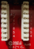
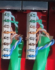
I have an IP camera that I want to use for license plate recognition. So I put a new Ethernet cable into the patch panel and created my own Ethernet connector on the other side of the cable which connects to the camera. However, I cannot see the camera using SADPTool (for testing I am using a Hickvision cam as it's laying outside on the floor but the final camera will be a Dahua from Andy). SADPTool has no problem seeing any of the other cameras. So clearly I am doing something wrong, most likely with the cabling. On the camera side I used 568B. But then I checked the patch panel that was done by a professional (I copied his outline) and I see that white green = pin 1, green = pin 2, white orange = pin 3, orange = pin 4, white brown = pin 5, brown = pin 6, white blue = pin 7, blue = pin 8. That neither matches 568A nor 568B. Is the patch panel manufacturer just routing signals differently on the PCB? And if so, how do I know if they use 568A for 568B?
 

Attachments

tangent

IPCT Contributor
Joined
May 12, 2016
Messages
4,421
Reaction score
3,655
Look a the silkscreen on the PCB and see what it says. It's hard to see in your picture, what looks like a faint "1" is visible. The question is: is the silk screen labeled 1-8 in order or do the number jump around?

If you can't visually follow the traces and figure it out, use a multimeter in ohm or continuity mode to figure out the relationship between the block and the RJ-45 (you can make a breakout cable of sorts it it helps).
 

rfj

Pulling my weight
Joined
Oct 26, 2014
Messages
402
Reaction score
117
It is a CableMatters but I don't know the model. Maybe E188100 (based on the picture). Anyways, now that I look at some unused ports (again, see attached image) it seems the pins are not in sequence. They are 1, 2, 3, 6, 7, 8, 5, 4.
 

Attachments

TonyR

IPCT Contributor
Joined
Jul 15, 2014
Messages
16,723
Reaction score
38,920
Location
Alabama
It is a CableMatters but I don't know the model. Maybe E188100 (based on the picture). Anyways, now that I look at some unused ports (again, see attached image) it seems the pins are not in sequence. They are 1, 2, 3, 6, 7, 8, 5, 4.
Then the panel is wired T-568A.
If it were T-568B then the G/W & G pair on 1/2 would be swapped with the O/W & O pair on 3/6
 

rfj

Pulling my weight
Joined
Oct 26, 2014
Messages
402
Reaction score
117
Ah, so I wired the camera wrong because I did 568B and the camera side.
 

tangent

IPCT Contributor
Joined
May 12, 2016
Messages
4,421
Reaction score
3,655
Both ends should match, but in theory of the switch is Auto MDI/MDX it ought to work. Though I can't recall if that actually works for PoE and am too tired to look it up.
 

TonyR

IPCT Contributor
Joined
Jul 15, 2014
Messages
16,723
Reaction score
38,920
Location
Alabama
Iirc wiring one end 568A and the other end 568B creates a cross-over cable.
It does but if the switch portion of the network devices are rated Auto MDI/MDX as mentioned by @tangent , it still should work.
That being said, it's best practice to make up both ends the same and in the U.S. of A. the predominate spec is T-568B.
 

eeeeesh

BIT Beta Team
Joined
Jan 5, 2017
Messages
412
Reaction score
681
When I wired my house in 2003, 586A which pretty much the standard for 'in the wall' type wiring and patch panels. That is how I did, now I just need to remember that if I ever have to change or move one of the original jacks
 

rfj

Pulling my weight
Joined
Oct 26, 2014
Messages
402
Reaction score
117
@TonyR Indeed, as you said in post #5, the patch panel is T-568A. And as you said in post #12 it was my understanding that in the USA we usually use T-568B. So I wired the camera end to T568B (not because of your post but because of what I read up before) while on the patch panel I followed what was done before (T-568A). I did redo the cable on the camera side and now it works. Thank you all very much for the feedback.
 
Top