Do USB wall warts have enough isolation to safely drive Raspberry Pi GPIO?

newfoundlandplucky

Getting the hang of it
Joined
Dec 1, 2018
Messages
87
Reaction score
86
Location
Ottawa
Am trying to incorporate Heath / Zenith motion sensing carriage lamps into a garage smart monitoring system. A USB wall wart adaptor is plugged into the carriage lamp controller as per the documentation. Just substituted a USB 5V wall wart in place of a light fixture. The wall wart is being used to detect AC line voltage from the carriage lamp motion controller.

Is it acceptable to connect the wall wart +5V and GND to a Raspberry Pi GPIO or should I provide more isolation? For some reason I hate the idea of wasting an isolation circuit for nothing. Is there a good way to test for isolation in the wall wart? Any help or advice appreciated.
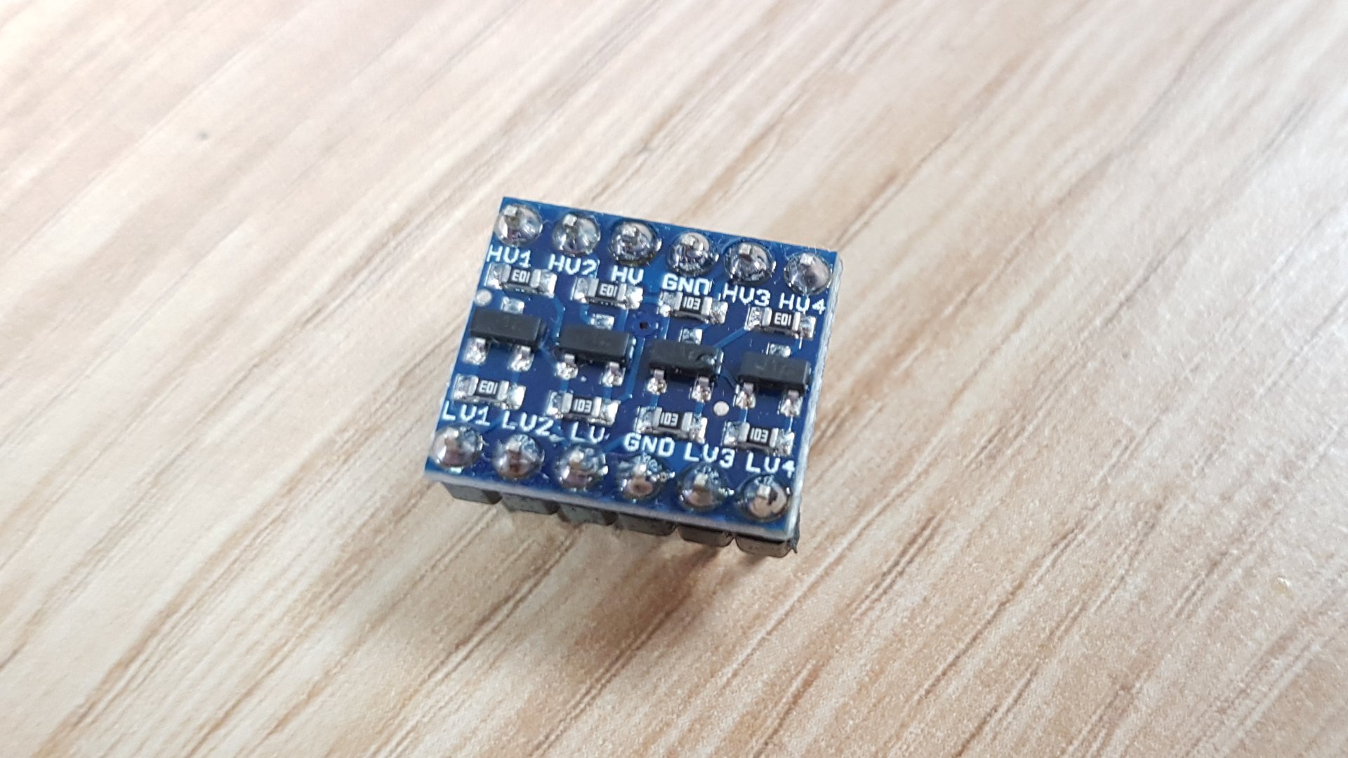
 

Attachments

tigerwillow1

Known around here
Joined
Jul 18, 2016
Messages
3,843
Reaction score
8,505
Location
USA, Oregon
I don't think anybody could answer if your walwart's output is isolated without testing it. Every one could be different. Most digital voltmeters have too high an input impedance to test for this. If you parallel something like a 1 meg resistor across the meter's input leads, then check for any voltage between all combinations between the walwart's input and output wires (while it's powered), I suspect that would be a pretty good test of isolation if all 4 readings showed zero volts, For positive isolation take a look at the PC817 optocoupler, which I'm using on a couple of input trigger interfaces to the NVR. It would work great with the walwart, or with the right resistor network and possibly half-wave rectifier, directly off the AC line. You can buy 10 of them, or even 50, from ebay and be able to burn out a few before getting it right. Another thing to look out for is if the motion sensor has a relay or electronic switched output. Some of the electronic switched outputs have a leakage current that would easily power the walwart even when switched off. An incandescent load will fix that.
 

tigerwillow1

Known around here
Joined
Jul 18, 2016
Messages
3,843
Reaction score
8,505
Location
USA, Oregon
Alternately, instead of a meg resistor in parallel on the leads of a DMM, buy a simple, old, analog VOM with an input impedance of under 100K.
I was afraid to say that because most people out there think you're an electrical backwoods hillbilly to think an analog meter is good for anything other than the trash. This is my impression and experience from an RV forum. Trying to explain why there's a voltage reading on an unloaded circuit is futile. If I could have only one (an unthinkable dilemma) I'd probably go with the analog meter.
 

sebastiantombs

Known around here
Joined
Dec 28, 2019
Messages
11,511
Reaction score
27,691
Location
New Jersey
I have a decent DMM but also have a decent VOM, unfortunately my Simpson 270 bit the dust many years ago as did my Senior VoltOhmist. Both, DMM and VOM, have their strengths and applications, but when you need a lower input Z a VOM is the only way to go and they're analog and not auto ranging. Stone age stuff, but reliable as hell.
 

newfoundlandplucky

Getting the hang of it
Joined
Dec 1, 2018
Messages
87
Reaction score
86
Location
Ottawa
I don't think anybody could answer if your walwart's output is isolated without testing it. Every one could be different.
Based on what you wrote I found a HaD article to monitor directly off the AC line. It may come to that. Not sure yet. I liked the HaD analysis but now I'm paranoid.

If the USB supply works then I'll build a jig and test the electrical isolation using your procedure. No way I'll know all of what to look for in a physical teardown. Hmmmm. Maybe just put the circuit in a metal junction box and hope for the best?

check this article
Doh! Yup, a level shifter could also provide the needed isolation. Thanks for the link.

I found a singleton relay in my electronics pile that uses a NEC 2705 opto. With this module the RPi is using its own GND and GPIO pull-up so guaranteed to be compatible. Will build a test circuit and see what happens.
 
Last edited:

newfoundlandplucky

Getting the hang of it
Joined
Dec 1, 2018
Messages
87
Reaction score
86
Location
Ottawa
I bought ten level shifting modules. Nice circuit to have in the toolbox. Worked out to less than $0.50 each shipped to my mailbox.
 

tigerwillow1

Known around here
Joined
Jul 18, 2016
Messages
3,843
Reaction score
8,505
Location
USA, Oregon
I'm not understanding how the level shifter provides isolation, because it requires one side of the wallwart output to be connected to the Pi's ground. Perhaps we're not thinking of "isolation" in the same terms. My definition of the wallwart's output being isolated is that it's not capable of conducting any appreciable current between either of its DC outputs and either of the hot or neutral of the AC power input. There's a perfectly possible best case that both the wallwart and Pi are each isolated, i.e. no problem. There's the less likely worst case of a disruptive ground loop, stuff going up in smoke, or shock hazard.

For what it's worth, I tested 2 USB wallwarts I have and both showed very good isolation. One is from a Samsung tablet and the other an LG phone. The Samsung is model #ETA0U61JWE, LG is model #MCS-02WD.
 

newfoundlandplucky

Getting the hang of it
Joined
Dec 1, 2018
Messages
87
Reaction score
86
Location
Ottawa
In truth I ordered the level shifting modules without looking to see if they also provided electrical isolation. There is a module with similar functionality that uses PC817 OPTO instead of the BSS138 FET but the cost is more than X10. I may end up ordering a bunch of naked PC817 ICs but haven't looked yet to see what support components are needed. Usually there are fully assembled Chinese modules available that are cheaper than mounting a bunch of stuff on a perfboard.

Thanks for the specific model references. That helps quite a bit. I love the inexpensive Chinese stuff for tinkering but I'd prefer not to have my garage burn down when the components begin to fail.
 

eggsan

Getting comfortable
Joined
Jul 24, 2015
Messages
619
Reaction score
528
it all depends on your particular project. I also keep a bunch of level shifting modules in my bag, not only for their lower cost (as compared to an opto), but also for its simplicity, The most important factor of using a level shifting is to protect the micro (always run those ports with 3.3V). I also have in my bag a bunch boards for down shifting from 12v to 3.3v. But when no contact is needed between output/input, there is no better way to isolate both ends, than using an opto
 

newfoundlandplucky

Getting the hang of it
Joined
Dec 1, 2018
Messages
87
Reaction score
86
Location
Ottawa
Thanks for your help. My prototype circuit worked perfectly.

Now I'm planning the actual installation. For insurance purposes I'll connect the motion control AC from the HZ4152 carriage lamps to a standard AC plug wired to code (painted yellow and labeled because of the special 360W limitation), get properly certified USB power adaptors, and then build a USB to microcontroller pin header cable with an embedded PC817B and resistor.

TL;DR USB wall warts have unknown electrical and physical isolation so buy a name brand but also employ best practice to isolate the microcontroller GPIO
 

Attachments

Top