michaelsandy
Young grasshopper
Hi,
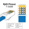
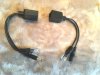
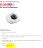
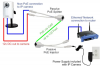
Am rigging up a DIY PoE injector cable, as i have lots of cable etc but don't know what voltage a 3 Mp Hikvision 2cd-2532f-IS is expecting... would it safely run on a 12v PoE input?
This is an older camera, obviously, circa 2015
It has separate 12v inputs, if not running via PoE...
Thanks
michaelsandy