Bricked NVR, nbd7024h-p need serial console help.

icebox

n3wb
Joined
Feb 13, 2016
Messages
22
Reaction score
8
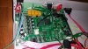
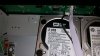
Anyone assist me with getting serial console going, on a nbd7024h-p
by Hangzhou Xiongmai Technology Co.

I updated the firmware, because the NVR gave me a message, update available with a pop up message saying update is available over the internet. I agreed but the NVR never came back, stuck on a reboot cycle. Shows the splash screen and reboots.
I do have a log of the start up from the serial console. Will post later, but it doesn't have much info, except Kernel is bad. (but no Tx to NVR)

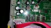
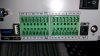
I know the 3 pins that are Rx,Tx,ground.
I tested ground pin to common ground by ohm meter.
And getting the Rx and Tx is trial and error, because there are only 2 pins left.
One has infinite resistance and the other is 5kohms.
The voltage changes but is like 1.7v for both I think, will check again later.
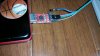
When I connect the ground, I get garbled output on Putty. I use the 115200,8bits,no parity, no flow control, but I can change to 7bits,etc and it still works.
But the ground connection kills it. Becomes garbled/gibberish immediately.
But interestingly leaving Rx and TX connected I have visual output/log of boot up.
Or even moving the Tx to ground and keeping Rx connected on the NVR, but the ground wire to the TTL/USB makes it garbled, I tired 2 diiferent TTL/USB just in case it was damaged, so I don't believe so.

And pressing Ctrl+C doesn't nothing.
probably no output from my computer/keyboard to the NVR.
The log shows Ctrl+C as the command to issue to interrupt the boot, and it is uboot.

Anyone suggestions???

I read this very good thread,Longse LS-N3525D Bricked.
Longse LS-N3525D Bricked
I tried contacting bheremans, but no response received. I also tired contacting the NVR company
Hangzhou Xiongmai Technology Co.,LTD.-00000107(NBD7024H-P)firmware, but no response, all I have is there sales email from their website.
Any help/advise would be greatly appreciated. I searched all over can't find, much info on this serial console problem.

Sincerely,
Jerry
 

alastairstevenson

Staff member
Joined
Oct 28, 2014
Messages
15,963
Reaction score
6,794
Location
Scotland
But the ground connection kills it. Becomes garbled/gibberish immediately.
But interestingly leaving Rx and TX connected I have visual output/log of boot up.
The symptoms suggest that what you believe is GND isn't.
What type of connections are on the board? If pads, usually the GND will be marked differently.

Suggestion:
Connect the GND of the serial TTL to USB convertor to the metal chassis.
Connect only the RX of the TTL to USB convertor to each of the 3 pins on the board until you find the one that generates data. That will be the TX on the board.
Connect the TX of the serial to TTL USB convertor to each of the other 2, and keeping Control-C pressed, power cycle the NVR and see if you can interrupt the startup, or get typed characters to echo. If you do, you have found the RX of the board.
The TX of the convertor will be short circuit proof, but only connect it for a short time while testing for the right pins.
 

icebox

n3wb
Joined
Feb 13, 2016
Messages
22
Reaction score
8
Thanks for assisting Alastairstevenson, really appreciate the input.
I tried what you said but it doesn't work, I used chassis ground to ground input on TTL-USB adapter and that messes everything up.
Only without a ground do I get an output to my computer screen from the NVR.
I tired every combo, using ground chasis to grnd pin on TTL-USB adapter and going to Rx of TTL-USB adapter from all 3 pins on the NVR and after that every possible combo
Rx/Tx/chasis to those 3 pins. 6 different possibilities.
I'm 100% on the pin that is ground and chassis, I have electrical experience. So continuity was good to a ground screw/chassis.

What works is connecting Rx on TTL-USB adapter to Tx (middle pin) on NVR (assuming correct) and connect Tx on TTL-USB adapter to Rx (square pad/most right) on NVR without a ground/chassis connection.

BTW still no interrupt. The pads I'm using have no mark unless it is on the otherside of board. I did solder a 3pin header to the board.
Perhaps my pcb is damaged? or I'm using the wrong Rx,Tx, Ground. It's marked JT12, one of the three pads is square, the others are circles. But it is not the ground, it is the TX, so I believe that is.

I wonder if anyone else ever had the problem where ground messes up the output to TTL-USB.
Also the timer is set to zero to interrupt the boot, may be it's not possible to interrupt with zero?

BTW output from the 3 pins is as follows, left to right. 0mV=ground, next -8.94vDC wow so high, and last the square pad 1.7vDC


Sincerely
Jerry

Log------->

U-Boot 2010.06-svn201 (Dec 05 2014 - 13:49:36)

Check spi flash controller v350... Found
Spi(cs1) ID: 0xC2 0x20 0x18 0xC2 0x20 0x18
Spi(cs1): Block:64KB Chip:16MB Name:"MX25L128XX"
In: serial
Out: serial
Err: serial
USB: scanning bus for devices... 1 USB Device(s) found
0 Storage Device(s) found
PHY 0x02: OUI = 0x1374, Model = 0x07, Rev = 0x02
change register for AR8035
CONFIG RGMII
PHY not link!
Press CTRL-C to abort autoboot in 0 seconds16384 KiB hi_sfc at 0:0 is now current device

CFG_BOOT_ADDR:0x0
### /UbootLogo UbootLogoload complete: 21986 bytes loaded to 0x88200000
jpeg decoding ...
<<addr=0x88200000, size=0xb85f9, vobuf=0x88200000>>
<<imgwidth=800, imgheight=600, linebytes=1600>>
decode success!!!!
decode jpeg success.
decode jpeg!

CFG_BOOT_ADDR:0x58050000
### boot LOAD ERROR<ffffffff> !
## Booting kernel from Legacy Image at 82000000 ...
Image Name: linux
Image Type: ARM Linux Kernel Image (uncompressed)
Data Size: 2808576 Bytes = 2.7 MiB
Load Address: 80008000
Entry Point: 80008000
Loading Kernel Image ... OK
OK

Starting kernel ...

data abort
pc : [<80008944>] lr : [<80007fff>]
sp : 802b6af8 ip : 0000001c fp : 802b6b14
r10: 60007fff r9 : 80008110 r8 : 80000100
r7 : 00001f40 r6 : 7ff237ff r5 : b5fbdfff r4 : 802b5ad4
r3 : 00001f40 r2 : 802c6b18 r1 : 802b6b18 r0 : 80008000
Flags: nzCv IRQs off FIQs off Mode SVC_32
Resetting CPU ...

resetting ...


U-Boot 2010.06-svn201 (Dec 05 2014 - 13:49:36)
 

alastairstevenson

Staff member
Joined
Oct 28, 2014
Messages
15,963
Reaction score
6,794
Location
Scotland
next -8.94vDC wow so high
This may suggest it's not TTL levels on the board serial connection, but classical RS232 levels.
That is not a TTL signal level, but is consistent with RS232 signal level.

TTL levels - 0 to +3v unipolar.
RS232 bipolar +-3v to +-15v

That may explain why you get a bad result with GND connected.

*edit*
Nice clear pictures, by the way.
Does JT19 go to a DB9 serial connector on the back panel?
JT20 looks similar.
 
Last edited:

icebox

n3wb
Joined
Feb 13, 2016
Messages
22
Reaction score
8
Thanks for compliment, JT20 is spare not being used. I tried that one. 4 pins. It has 5v right most right by JT20 mark. 2 middle pins about 1.7v, the far left is gnd.
JT19 goes to another pcb on the front of the NVR for controls like selecting channel, fast forward etc, but it also has a USB port, so maybe that's what it is.
I do have alarm inputs on back one/two have rx/tx I will try those later?20170425_055059.jpg
Attached picture.
I guess I should still be looking for the correct voltage levels on the board.20170425_054217.jpg
 
Last edited:

alastairstevenson

Staff member
Joined
Oct 28, 2014
Messages
15,963
Reaction score
6,794
Location
Scotland
I tried that one.
Tried it for testing voltages - or for serial activity?
JT20 is spare not being used. I tried that one. 4 pins. It has 5v right most right by JT20 mark. 2 middle pins about 1.7v, the far left is gnd.
I'd say that's a candidate for a serial TTL connection. Certainly all the voltages match.
If you haven't already done so - maybe probe the middle 2 pins with the RX lead - with GND connected.
You would need to power cycle the NVR to see activity - but you know that ...
 

icebox

n3wb
Joined
Feb 13, 2016
Messages
22
Reaction score
8
Hey alastairstevenson, thanks again, I tried already but did it again, I probed both JT20 and JT19 it didn't work, no output at all to putty.
I tried connecting my old laptop serial DB9 port to the JT12 connection, it didn't work, I thought may be like you said it's not TTL, but higher voltages.
I hope I didn't fry the board. I couldn't get any output to the old laptop even using the TTL-USB adapter as I normally do to get an output.
I tried the back ports, green box that has Rx/Tx, RS232, it is basically the same as JT12 it has the same voltages 1.7v and -8.9v.
I was reading Serial Console [OpenWrt Wiki] website that said it's possible to change the modes of the serial console by shorting pins or applying voltages to some pins, may be that's
what I did by accident, as I remember checking the voltage at the pin that now reads -8.9v steadily was actually 1.7v before! I think I'm running out of options, wish I could just buy a new replacement board, to get this fixed.
If I figure anything out I'll be sure to post.
Sincerely,
Jerry
 

icebox

n3wb
Joined
Feb 13, 2016
Messages
22
Reaction score
8
Holy cow I got in, thank you alastairstevenson. It was a bad connection using the DB9 on my old laptop. The 3pin header is rs232 with higher inverted voltage. If only I had a image file I could upload to the NVR to get it to stop rebooting. I'm really not Linux savy, could someone provide some suggestions? Besides calling the NVR manufacturer for the recovery file, a generic file I could try to upload using tftp program.20170426_191847.jpg
 

alastairstevenson

Staff member
Joined
Oct 28, 2014
Messages
15,963
Reaction score
6,794
Location
Scotland
It looks like you may have a chance of figuring out the cause of the problem.
Fixing it may be another matter though.

Suggestion:
First of all, discover the 'Copy rollback to clipboard' facility in PuTTY, click the icon in the top left of its window.
Then you can paste the resulting text into Notepad or similar to edit / save / post etc.
And you will find the 'CODE' tags in the forum work well for long sections of copied text, under the '+' sign of the edit menu. Much easier all round than dealing with images.

At the u-boot prompt, see what commands it has with 'help'.
The 'show' command will be useful.
See if 'show ptb' exists, that may give an indication of the state of the flash partitions, which may be corrupted.

But any recovery (assuming it's a firmware corruption problem and not hardware) doesn't just depend on having facilities within u-boot, but having some image data / firmware for the specific model.
 

icebox

n3wb
Joined
Feb 13, 2016
Messages
22
Reaction score
8
I apologize for my ill-mannered forum etiquette. Not reading forum rules.
I will try to copy instead of taking pictures and tag it appropriately.
Unfortunately there is no show command.
Code:
hisilicon # show ptb
Unknown command 'show' - try 'help'
'Help' yields the following:
Code:
hisilicon # help
?       - alias for 'help'
base    - print or set address offset
bootm   - boot application image from memory
bootp   - boot image via network using BOOTP/TFTP protocol
cmp     - memory compare
cp      - memory copy
crc32   - checksum calculation
ddr     - ddr training function
decjpg  - jpgd   - decode jpeg picture.

ext2load- load binary file from a Ext2 filesystem
ext2ls  - list files in a directory (default /)
fatinfo - print information about filesystem
fatload - load binary file from a dos filesystem
fatls   - list files in a directory (default /)
fload   - fload  - load binary file from a filesystem image for system boot

flwrite - SPI flash sub-system
getinfo - print hardware information
go      - start application at address 'addr'
help    - print command description/usage
lip     - lip      - set local ip address but not save to flash

lload   - lload  - load logo file

loadb   - load binary file over serial line (kermit mode)
loady   - load binary file over serial line (ymodem mode)
logoload- logoload  - load binary file from a filesystem image for system boot

loop    - infinite loop on address range
mac     - mac      - set mac address and save to flash

md      - memory display
mii     - MII utility commands
mm      - memory modify (auto-incrementing address)
mtest   - simple RAM read/write test
mw      - memory write (fill)
nm      - memory modify (constant address)
ping    - send ICMP ECHO_REQUEST to network host
printenv- print environment variables
rarpboot- boot image via network using RARP/TFTP protocol
reset   - Perform RESET of the CPU
run     - run commands in an environment variable
saveenv - save environment variables to persistent storage
setenv  - set environment variables
setvobg - setvobg   - set vo backgroud color.
        - setvobg [dev color]
sf      - SPI flash sub-system
sip     - sip      - set server ip address but not save to flash

startgx - startgx   - open graphics layer.
        - startgx [layer addr stride x y w h]

startvo - startvo   - open interface of vo device.
        - startvo [dev type sync]
stopgx  - stopgx   - close graphics layer.
        - stopgx [layer]
stopvo  - stopvo   - close interface of vo device.
        - stopvo [dev]
tftp    - tftp  - download or upload image via network using TFTP protocol
usb     - USB sub-system
usbboot - boot from USB device
version - print monitor version
hisilicon #
Yes the only firmware I have is the one that they provide on their website as I linked in my first post. That's why I was hoping someone could may be dissect it for me, make it usable from a recovery console standpoint as oppose to a web gui firmware update. Possibly a Uimage file or whatever might be needed with the correct checksum.
I tried a couple things but I'm not knowledgeable to go any further without some coaching.
Code:
hisilicon #
printenv
bootcmd=sf probe 0;sf read 84000000 f20000 20000;logoload 0x84000000;decjpg;sf read 84000000 50000 4A0000;fload 84000000;bootm 0x82000000
bootdelay=1
baudrate=115200
bootfile="uImage"
restore=1
da=mw.b 0x82000000 ff 1000000;tftp 0x82000000 u-boot.bin.img;sf probe 0;flwrite
du=mw.b 0x82000000 ff 1000000;tftp 0x82000000 user-x.cramfs.img;sf probe 0;flwrite
dr=mw.b 0x82000000 ff 1000000;tftp 0x82000000 romfs-x.cramfs.img;sf probe 0;flwrite
dw=mw.b 0x82000000 ff 1000000;tftp 0x82000000 web-x.cramfs.img;sf probe 0;flwrite
dl=mw.b 0x82000000 ff 1000000;tftp 0x82000000 logo-x.cramfs.img;sf probe 0;flwrite
dc=mw.b 0x82000000 ff 1000000;tftp 0x82000000 custom-x.cramfs.img;sf probe 0;flwrite
up=mw.b 0x82000000 ff 1000000;tftp 0x82000000 update.img;sf probe 0;flwrite
tk=mw.b 0x82000000 ff 1000000;tftp 0x82000000 zImage.img; bootm 0x82000000
dd=mw.b 0x82000000 ff 1000000;tftp 0x82000000 mtd-x.jffs2.img;sf probe 0;flwrite
ipaddr=192.168.1.10
serverip=192.168.1.1
netmask=255.255.255.0
gatewayip=192.168.0.1
ethaddr=00:0b:3f:00:00:01
bootargs=mem=180M console=ttyAMA0,115200 root=/dev/mtdblock1 rootfstype=cramfs mtdparts=hi_sfc:320K(boot),4736K(romfs),5824K(usr),1536K(web),3072K(custom),128K(logo),768K(mtd)
appSystemLanguage=English
appVideoStandard=NTSC
stdin=serial
stdout=serial
stderr=serial
verify=n
ver=U-Boot 2010.06-svn201 (Dec 05 2014 - 13:49:36)

Environment size: 1359/65532 bytes
hisilicon #
I see that my NVR ip address is 192.168.1.10, so I set my windows xp pc (one with the serial console) to 192.168.1.1 and (default gateway to 192.168.0.1 as it doesn't matter I believe.) subnet mask 255.255.255.0
I'm going by the output of command printenv

So I connected both by a network switch, standalone network, no internet access,etc.

Then I tried to ping the NVR it failed, the only time it worked was when the NVR was pinging a unreachable host (from the serial console I would type 'ping 192.168.1.10 or whatever)
for some reason the NVR can not ping itself, but can ping my pc at 192.168.1.1 sucessfully.

Then I would try to telnet to NVR/192.168.1.10 it would fail from command prompt on windows pc.
I ran tftp server on my windows pc, hosted a file (the firmware from NVR website)
I typed:
"tftp" on serial console, it tried to connect but said no file available.
I then typed "run up" that failed as well 'stating no update.img file found'

Results of pinging follow:
Code:
C:\Documents and Settings\Administrator>ping 192.168.1.10

Pinging 192.168.1.10 with 32 bytes of data:

Request timed out.
Request timed out.
Request timed out.
Reply from 192.168.1.10: bytes=32 time<1ms TTL=128

Ping statistics for 192.168.1.10:
    Packets: Sent = 4, Received = 1, Lost = 3 (75% loss),
Approximate round trip times in milli-seconds:
    Minimum = 0ms, Maximum = 0ms, Average = 0ms

C:\Documents and Settings\Administrator>ping 192.168.1.10

Pinging 192.168.1.10 with 32 bytes of data:

Reply from 192.168.1.10: bytes=32 time<1ms TTL=128

Ping statistics for 192.168.1.10:
    Packets: Sent = 4, Received = 4, Lost = 0 (0% loss),
Approximate round trip times in milli-seconds:
    Minimum = 0ms, Maximum = 0ms, Average = 0ms

C:\Documents and Settings\Administrator>telnet 192.168.1.10
Connecting To 192.168.1.10...Could not open connection to the host, on port 23:
Connect failed

C:\Documents and Settings\Administrator>ping 192.168.1.10

Pinging 192.168.1.10 with 32 bytes of data:

Reply from 192.168.1.10: bytes=32 time<1ms TTL=128
Reply from 192.168.1.10: bytes=32 time=15ms TTL=128
Reply from 192.168.1.10: bytes=32 time<1ms TTL=128

Ping statistics for 192.168.1.10:
    Packets: Sent = 4, Received = 4, Lost = 0 (0% loss),
Approximate round trip times in milli-seconds:
    Minimum = 0ms, Maximum = 15ms, Average = 3ms

C:\Documents and Settings\Administrator>telnet 192.168.1.10
Connecting To 192.168.1.10...Could not open connection to the host, on port 23:
Connect failed

C:\Documents and Settings\Administrator>telnet 192.168.1.10
Connecting To 192.168.1.10...Could not open connection to the host, on port 23:
Connect failed

C:\Documents and Settings\Administrator>ping 192.168.1.10

Pinging 192.168.1.10 with 32 bytes of data:

Reply from 192.168.1.10: bytes=32 time<1ms TTL=128

Ping statistics for 192.168.1.10:
    Packets: Sent = 4, Received = 4, Lost = 0 (0% loss),
Approximate round trip times in milli-seconds:
    Minimum = 0ms, Maximum = 0ms, Average = 0ms

C:\Documents and Settings\Administrator>
I tried a program called Devicemanger from this manufacturer for their top201 camera, It searches out their devices on the network and can provide a firmware update through the program but it does not see the nvr on the network through an IP search. This program would find the NVR and all my top201 cameras no problem before, so it should be compatible.

But that's it, not sure what else I can do.
May be I should start a new thread/topic in the firmware section in this forum as now I'm off topic from my original question, no longer looking for serial console access, but recovery firmware.
 
Last edited:

alastairstevenson

Staff member
Joined
Oct 28, 2014
Messages
15,963
Reaction score
6,794
Location
Scotland
That looks like a full-featured u-boot on your NVR, with predefined commands associated with recovery and update.
By the way - u-boot is primarily a bootloader, so don't be surprised that you can't do things with it such as telnet, or finding it with a search tool as you would be able to do when a full system is running.

At the moment it's not clear what recovery steps are required.
You have a working bootloader, and access to it.

On the startup there is an error, the meaning and significance of which is currently unknown.
Then the Linux kernel is loaded and started but causes a data abort.
This is probably from accessing RAM that does not exist or has not been mapped or is invalid in some way.
Is this linked to the earlier 'LOAD ERROR' would be a question. Or is the kernel image corrupt?
CFG_BOOT_ADDR:0x58050000
### boot LOAD ERROR<ffffffff> !
## Booting kernel from Legacy Image at 82000000 ...
Image Name: linux
Image Type: ARM Linux Kernel Image (uncompressed)
Data Size: 2808576 Bytes = 2.7 MiB
Load Address: 80008000
Entry Point: 80008000
Loading Kernel Image ... OK
OK

Starting kernel ...

data abort
On the face of it, there are u-boot environment variables pre-loaded with the commands to write images to flash.
Potentially these could be used with the tftp server on your PC.
If you unzip the .bin file from the manufacturer link in your first post, you will find a set of u-boot format image files:
Code:
alastair@PC-I5 ~/cctv/nbd7024h-p $ ll
total 24568
drwxr-xr-x  2 alastair alastair     4096 Apr 28 08:22 ./
drwxr-xr-x 17 alastair alastair     4096 Apr 28 08:20 ../
-rw-r--r--  1 alastair alastair  2891840 Dec  6 05:21 custom-x.cramfs.img
-rw-r--r--  1 alastair alastair 12547513 Apr 28 08:19 General_General_NBD7024H-P_V4.02.R11.3070.Nat.OnvifC.20161206.bin
-rwxr-xr-x  1 alastair alastair      480 Dec  6 05:21 InstallDesc*
-rw-r--r--  1 alastair alastair    20544 Dec  6 05:21 logo-x.cramfs.img
-rw-r--r--  1 alastair alastair  3989568 Dec  6 05:21 romfs-x.cramfs.img
-rw-r--r--  1 alastair alastair  4382784 Dec  6 05:21 user-x.cramfs.img
-rw-r--r--  1 alastair alastair  1286208 Dec  6 05:21 web-x.cramfs.img
-rw-r--r--  1 alastair alastair      177 Apr 28 08:15 更新说明.txt
alastair@PC-I5 ~/cctv/nbd7024h-p $ file *
custom-x.cramfs.img:                                               u-boot legacy uImage, linux, Linux/ARM, Standalone Program (gzip), 2891776 bytes, Tue Dec  6 05:20:50 2016, Load Address: 0x00C20000, Entry Point: 0x00F20000, Header CRC: 0x71E0F1B0, Data CRC: 0x121CDE09
General_General_NBD7024H-P_V4.02.R11.3070.Nat.OnvifC.20161206.bin: Zip archive data, at least v2.0 to extract
InstallDesc:                                                       ASCII text
logo-x.cramfs.img:                                                 u-boot legacy uImage, linux, Linux/ARM, Standalone Program (gzip), 20480 bytes, Tue Dec  6 05:20:46 2016, Load Address: 0x00F20000, Entry Point: 0x00F40000, Header CRC: 0xB8552444, Data CRC: 0x8E3FDB50
romfs-x.cramfs.img:                                                u-boot legacy uImage, linux, Linux/ARM, OS Kernel Image (gzip), 3989504 bytes, Tue Dec  6 05:21:00 2016, Load Address: 0x00050000, Entry Point: 0x004F0000, Header CRC: 0xDF330DB9, Data CRC: 0x38B30D92
user-x.cramfs.img:                                                 u-boot legacy uImage, linux, Linux/ARM, OS Kernel Image (gzip), 4382720 bytes, Tue Dec  6 05:20:58 2016, Load Address: 0x004F0000, Entry Point: 0x00AA0000, Header CRC: 0x948E3E2B, Data CRC: 0x94B69E8F
web-x.cramfs.img:                                                  u-boot legacy uImage, linux, Linux/ARM, Standalone Program (gzip), 1286144 bytes, Tue Dec  6 05:20:51 2016, Load Address: 0x00AA0000, Entry Point: 0x00C20000, Header CRC: 0x3E5EF6C9, Data CRC: 0x7B76ACD9
更新说明.txt:                                                      ISO-8859 text, with CRLF line terminators
alastair@PC-I5 ~/cctv/nbd7024h-p $
Unfortunately - there is not a kernel image, these are the root file system and app-related files, so if the kernel in the flash is corrupt that firmware doesn't provide the chance to re-flash it. I'd suggest that the kernel startup hasn't got far enough to access any data associated with the available images, as it would normally give some progress messages from it's own uncompressor before that point.
I think you need a kernel image, which may be in the 'update.img' file referenced but unavailable.
The 'run tk' u-boot command is aimed at booting a zImage (that's a uImage kernel after the header has been stripped off) over the network with tftp.
 

icebox

n3wb
Joined
Feb 13, 2016
Messages
22
Reaction score
8
Thank you for that treasure trove of information,:secret: 
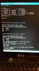
I did a lot of googling today and not much was discovered on the kernel.
Too bad can't get a hold of the zImage for this board/NVR. Thank you for your time and explaining it so well, to me and everyone reading in the shadows.

If I can figure out how to backup my kernel,bootloader,etc.
That will be my next step, just not to mess things up worse.
I googled some stuff but not sure if I can mount a NFS share or TFTP it to my windows pc, I don't think the network connection will work.
Probably have to copy it for the serial console some how and convert to binary?

I forgot to mention, even though I can successfully interrupt the bootloader. After about 5 minutes or less
the NVR will continue to go into the boot cycle again and I have to interrupt it again.
Is there a command that can prevent this?
Is this normal?
I see this as a problem if trying to flash something to the NVR in the future.

FYI
I did try to call Hangzhou Xiongmai Technology Co.
The first # on website leads you to automated answering service with a choice of language selection but it would not be able to understand my selection of english by pressing 4. I think it may be because I had a bad phone connection, I used poptox.com to call for free, it has a limit of 7.5minutes it is not that good of a service.
The other # I called someone answered in Mandarin possibly, but once I started speaking english they hung up on me.
Emailing the company 3 times and they never reply, @ oversea_sales@xiongmaitech.com
Will try to call again later if can find a better phone service.
 
Last edited:

alastairstevenson

Staff member
Joined
Oct 28, 2014
Messages
15,963
Reaction score
6,794
Location
Scotland
I forgot to mention, even though I can successfully interrupt the bootloader. After about 5 minutes or less
the NVR will continue to go into the boot cycle again and I have to interrupt it again.
Is there a command that can prevent this?
Is this normal?
I have not seen this before, I'm not sure if you can inhibit the behaviour.

If I was trying to fix this - my next step would be trying the firmware updates to see if any change to the startup occurs.
It sounds like you already have a tftp server on the PC.
You'd need to unzip the firmware files into the same folder as the tftp server.
Then at the u-boot prompt, a 'run dl' may attempt to update the logo, for example.
 

bheremans

Young grasshopper
Joined
Nov 11, 2015
Messages
38
Reaction score
5
Hi, I didn't have a good firmware either. I actually got it from the longse / herospeed site. After viewing it with an editor i found out it was cramfs file with a litte header that I striped..
But it was alastairstevenson who provided me the different files. I could find the hashes and file sizes with an editor in the file itself.
After that I got the correct sizes I dowloaded and flashed them with the commands provided in the other post. But I don't think the files will have to be flashed to the same adresses...
 

icebox

n3wb
Joined
Feb 13, 2016
Messages
22
Reaction score
8
Oh I see, bheremans you basically pulled out a kernel image/recovery.img? from the romfs-x.cramfs.img. Great cool.
I found some older firmware files online today for this NVR, but all are missing the
mtd-x.jffs2.img
zImage.img
update.img
files
but one of them had the
u-boot.bin.img which is cool but no use I suppose.
I still didn't get around to try to flash the
logo-x.cramfs.img, sorry
alastairstevenson will try today, if I can get a few moments when I get home.
hoping it works to have some hope.
Was researching how/if possible to back up my current set up.
But I don't see how, as I don't understand memory addresses/ram/offsets/flash etc.
Thanks to you both
Will update later.
 

icebox

n3wb
Joined
Feb 13, 2016
Messages
22
Reaction score
8
Does this look good? I guess it worked, except may be for the PACK_ID error.
After uploading this the NVR continues to the reboot cycle, even without me typing "reset" it just started rebooting again.
Code:
hisilicon # run dl
miiphy_register: non unique device name '0:2'
PHY 0x02: OUI = 0x1374, Model = 0x07, Rev = 0x02
change register for AR8035
CONFIG RGMII
MAC:   00-0B-3F-00-00-01
TFTP from server 192.168.1.1; our IP address is 192.168.1.10
Download Filename 'logo-x.cramfs.img'.
Download to address: 0x82000000
Downloading: #################################################
done
Bytes transferred = 20544 (5040 hex)
16384 KiB hi_sfc at 0:0 is now current device
PACK_ID error

## Checking Image at 0x82000000 ...
   Header CRC Checking ... OK
   Image Name:   linux
   Image Type:   ARM Linux Standalone Program (gzip compressed)
   Data Size:    20480 Bytes = 20 KiB
   Load Address: 00f20000
   Entry Point:  00f40000
   Data CRC Checking ... OK
Programing start at: 0x00f20000
Programing end at: 0x00f40000
Erasing at 0xf40000 -- 100% complete.
done.
Erased sectors.
Saving Image to Flash ...
Writing at 0xf40000 -- 100% complete.
done.
 

icebox

n3wb
Joined
Feb 13, 2016
Messages
22
Reaction score
8
Very happy to say, my NVR is fully functional again, thanks to
jftech.com support. I owe them, so grateful. They sent me the needed update.img file, which I copied over to my NVR by TFTP, running command "run up" from serial console and having the update file inside the same directory as TFTP server on my windows pc.
It did it in under 5minutes thankfully before the NVR would automatically reboot.
So I'm very thankful to alastairstevenson guiding me as well, when no one else could or would.
Thank you!
I tried to upload file here, but it would fail, I guess it's too big.
If anyone needs it, let me know, I'll gladly share it.

All my settings like cameras/password were all retained, didn't lose anything.
The serial output from the flash:
Code:
U-Boot 2010.06-svn201 (Dec 05 2014 - 13:49:36)

Check spi flash controller v350... Found
Spi(cs1) ID: 0xC2 0x20 0x18 0xC2 0x20 0x18
Spi(cs1): Block:64KB Chip:16MB Name:"MX25L128XX"
In:    serial
Out:   serial
Err:   serial
USB:   scanning bus for devices... 1 USB Device(s) found
0 Storage Device(s) found
PHY 0x02: OUI = 0x1374, Model = 0x07, Rev = 0x02
change register for AR8035
CONFIG RGMII
MAC:   00-0B-3F-00-00-01
Press CTRL-C to abort autoboot in 0 secondshisilicon # printenv
bootcmd=sf probe 0;sf read 84000000 f20000 20000;logoload 0x84000000;decjpg;sf read 84000000 50000 4A0000;fload 84000000;bootm 0x82000000
bootdelay=1
baudrate=115200
bootfile="uImage"
restore=1
da=mw.b 0x82000000 ff 1000000;tftp 0x82000000 u-boot.bin.img;sf probe 0;flwrite
du=mw.b 0x82000000 ff 1000000;tftp 0x82000000 user-x.cramfs.img;sf probe 0;flwrite
dr=mw.b 0x82000000 ff 1000000;tftp 0x82000000 romfs-x.cramfs.img;sf probe 0;flwrite
dw=mw.b 0x82000000 ff 1000000;tftp 0x82000000 web-x.cramfs.img;sf probe 0;flwrite
dl=mw.b 0x82000000 ff 1000000;tftp 0x82000000 logo-x.cramfs.img;sf probe 0;flwrite
dc=mw.b 0x82000000 ff 1000000;tftp 0x82000000 custom-x.cramfs.img;sf probe 0;flwrite
up=mw.b 0x82000000 ff 1000000;tftp 0x82000000 update.img;sf probe 0;flwrite
tk=mw.b 0x82000000 ff 1000000;tftp 0x82000000 zImage.img; bootm 0x82000000
dd=mw.b 0x82000000 ff 1000000;tftp 0x82000000 mtd-x.jffs2.img;sf probe 0;flwrite
ipaddr=192.168.1.10
serverip=192.168.1.1
netmask=255.255.255.0
gatewayip=192.168.0.1
ethaddr=00:0b:3f:00:00:01
bootargs=mem=180M console=ttyAMA0,115200 root=/dev/mtdblock1 rootfstype=cramfs mtdparts=hi_sfc:320K(boot),4736K(romfs),5824K(usr),1536K(web),3072K(custom),128K(logo),768K(mtd)
appSystemLanguage=English
appVideoStandard=NTSC
stdin=serial
stdout=serial
stderr=serial
verify=n
ver=U-Boot 2010.06-svn201 (Dec 05 2014 - 13:49:36)

Environment size: 1359/65532 bytes
hisilicon # run up
miiphy_register: non unique device name '0:2'
PHY 0x02: OUI = 0x1374, Model = 0x07, Rev = 0x02
change register for AR8035
CONFIG RGMII
MAC:   00-0B-3F-00-00-01
TFTP from server 192.168.1.1; our IP address is 192.168.1.10
Download Filename 'update.img'.
Download to address: 0x82000000
Downloading: #################################################
done
Bytes transferred = 12652928 (c11180 hex)
16384 KiB hi_sfc at 0:0 is now current device
PACK_ID OK

## Checking Image at 0x82000040 ...
   Header CRC Checking ... OK
   Image Name:   linux
   Image Type:   ARM Linux Standalone Program (gzip compressed)
   Data Size:    2920448 Bytes = 2.8 MiB
   Load Address: 00c20000
   Entry Point:  00f20000
   Data CRC Checking ... OK
Programing start at: 0x00c20000
Programing end at: 0x00f20000
Erasing at 0xf20000 -- 100% complete.
done.
Erased sectors.
Saving Image to Flash ...
Writing at 0xf20000 -- 100% complete.
done.
PACK_ID OK

## Checking Image at 0x822c9080 ...
   Header CRC Checking ... OK
   Image Name:   linux
   Image Type:   ARM Linux Standalone Program (gzip compressed)
   Data Size:    20480 Bytes = 20 KiB
   Load Address: 00f20000
   Entry Point:  00f40000
   Data CRC Checking ... OK
Programing start at: 0x00f20000
Programing end at: 0x00f40000
Erasing at 0xf40000 -- 100% complete.
done.
Erased sectors.
Saving Image to Flash ...
Writing at 0xf40000 -- 100% complete.
done.
PACK_ID OK

## Checking Image at 0x822ce0c0 ...
   Header CRC Checking ... OK
   Image Name:   linux
   Image Type:   ARM Linux Kernel Image (gzip compressed)
   Data Size:    3989504 Bytes = 3.8 MiB
   Load Address: 00050000
   Entry Point:  004f0000
   Data CRC Checking ... OK
Programing start at: 0x00050000
Programing end at: 0x004f0000
Erasing at 0x4f0000 -- 100% complete.
done.
Erased sectors.
Saving Image to Flash ...
Writing at 0x4f0000 -- 100% complete.
done.
PACK_ID OK

## Checking Image at 0x8269c100 ...
   Header CRC Checking ... OK
   Image Name:   linux
   Image Type:   ARM Linux Kernel Image (gzip compressed)
   Data Size:    4411392 Bytes = 4.2 MiB
   Load Address: 004f0000
   Entry Point:  00aa0000
   Data CRC Checking ... OK
Programing start at: 0x004f0000
Programing end at: 0x00aa0000
Erasing at 0xaa0000 -- 100% complete.
done.
Erased sectors.
Saving Image to Flash ...
Writing at 0xaa0000 -- 100% complete.
done.
PACK_ID OK

## Checking Image at 0x82ad1140 ...
   Header CRC Checking ... OK
   Image Name:   linux
   Image Type:   ARM Linux Standalone Program (gzip compressed)
   Data Size:    1310720 Bytes = 1.3 MiB
   Load Address: 00aa0000
   Entry Point:  00c20000
   Data CRC Checking ... OK
Programing start at: 0x00aa0000
Programing end at: 0x00c20000
Erasing at 0xc20000 -- 100% complete.
done.
Erased sectors.
Saving Image to Flash ...
Writing at 0xc20000 -- 100% complete.
done.
hisilicon # reset
resetting ...
A fresh start, with the NVR starting up correctly:
Code:
U-Boot 2010.06-svn201 (Dec 05 2014 - 13:49:36)

Check spi flash controller v350... Found
Spi(cs1) ID: 0xC2 0x20 0x18 0xC2 0x20 0x18
Spi(cs1): Block:64KB Chip:16MB Name:"MX25L128XX"
In:    serial
Out:   serial
Err:   serial
USB:   scanning bus for devices... 1 USB Device(s) found
0 Storage Device(s) found
PHY 0x02: OUI = 0x1374, Model = 0x07, Rev = 0x02
change register for AR8035
CONFIG RGMII
MAC:   00-0B-3F-00-00-01
Press CTRL-C to abort autoboot in 0 seconds16384 KiB hi_sfc at 0:0 is now current device

CFG_BOOT_ADDR:0x0
### /UbootLogo UbootLogoload complete: 21986 bytes loaded to 0x88200000
jpeg decoding ...
<<addr=0x88200000, size=0xb85f9, vobuf=0x88200000>>
<<imgwidth=800, imgheight=600, linebytes=1600>>
decode success!!!!
decode jpeg success.
decode jpeg!

CFG_BOOT_ADDR:0x58050000
### boot load complete: 2808640 bytes loaded to 0x82000000
### SAVE TO 80008000 !
## Booting kernel from Legacy Image at 82000000 ...
   Image Name:   linux
   Image Type:   ARM Linux Kernel Image (uncompressed)
   Data Size:    2808576 Bytes = 2.7 MiB
   Load Address: 80008000
   Entry Point:  80008000
   Loading Kernel Image ... OK
OK

Starting kernel ...

Uncompressing Linux... done, booting the kernel.
 
Top